На сайте 123377 инструкций общим размером 499.27 Гб , которые состоят из 6233966 страниц
Фото
Руководство пользователя TRIPP LITE B021-000-19. Основные функции, характеристики и условия эксплуатации изложены на 12 страницах документа в pdf формате.
Доступно к просмотру 12 страниц. Рекомендуем вам скачать файл инструкции, поскольку онлайн просмотр документа может сильно отличаться от оригинала.
Owner’s Manual
1U Rackmount Console
(for KVM Switch or Server)
Models:
B021-000-17 & B021-000-19
Series No:
AGCB6533
Espanol       p. 5          Francais       p. 9
Package Contents
• 1U Rackmount Console                                  • AC Power Cord
• KVM Cable Kit (VGA, PS/2)                             • Owner’s Manual
• PS/2 to USB Adapter                                   • Mounting Brackets
Overview
Tripp Lite's 1U Rackmount Console features an integrated LCD monitor, full keyboard and touch pad in a 1U rackmountable housing. This console is
designed for use with a server or a KVM switch with PS/2 console connectors. A PS/2 to USB adapter is included to connect to a USB KVM or server.
Features
•  Rackmount console (LCD monitor, keyboard, touch pad) in an integrated 1U rackmountable housing
• Sleep mode when the monitor cover is closed
• Rackmountable in standard 19-inch rack (1U)
• Includes rackmount brackets
• Supports resolutions up to 1366 x 768 pixels
• Includes a USB 2.0 Pass-Through port which can be used to provide easy access to a USB port on a connected device (KVM switch or
computer)
SAVE THESE INSTRUCTIONS
This manual contains important instructions that should be followed during the installation and operation of the rackmount console
described in this manual. Read all instructions thoroughly before attempting to install or operate the rackmount console. Failure to comply
will void the warranty and could damage the rackmount console or connected equipment.
WARNING:
Use of this equipment in life support applications where failure of this equipment can reasonably be expected to cause the failure of the
life support equipment or to significantly affect its safety or effectiveness is not recommended. Do not use this equipment in the presence
of a flammable anesthetic mixture with air, oxygen or nitrous oxide.
PROTECT YOUR INVESTMENT!
Register your product for quicker service and ultimate peace of mind.
You could also win an ISOBAR6ULTRA surge protector—a $50 value!
www.tripplite.com/warranty
1111 West 35th Street, Chicago, IL 60609 USA • www.tripplite.com/support
Copyright © 2014 Tripp Lite. All rights reserved. All trademarks are the property of their respective owners.
1
The policy of Tripp Lite is one of continuous improvement. Specifications are subject to change without notice.
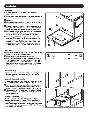
Introduction
Front View
1   Handle: Pull to slide the module out; push to slide the
module in.
1
2    LCD Monitor: After sliding the module out, flip up the cover to   2
access the LCD monitor, keyboard and touch pad.
3    Keyboard
4    Rackmounting Brackets: The brackets secure the chassis to
a standard 19-inch rack or rack enclosure.
6
5    2-Button Touchpad: Press the left button to left-click, press
the right button to right-click. Scroll up and down the screen by
running finger up or down the far right side of the touchpad.  3
6    Console and LCD Controls: The controls located here include
the console power On/Off button, and the buttons used to
control the position and picture setting of the LCD display.
7    Pass-Through USB Port: This port is inactive until a USB A
Male/Male cable (Tripp Lite model UR020-Series) is used to
connect the Pass-Through port on the back of the console to a
USB port on a computer or KVM switch. When active, a USB                                           4
device connected to the front of the console will then be
available for use with the connected computer or KVM switch.  7    5
Rear View
1   Console Port Section: Connects the console to your server or
KVM switch with the included KVM cable kit.
2   Power Socket: The AC power cord plugs in here.
3    Pass-Through USB Port: This port is connected to the Pass-    2                     3        1
Through USB port on the front of the console. The front Pass-
Through port is active when a USB A Male/Male cable (Tripp Lite
model UR020-Series) is connected between the Pass-Through
port on the back and a USB port on a KVM or server.
Rackmounting
Tripp Lite's 1U Rackmount Console is designed for mounting in a 1U
rack system. The various mounting options are explained in the
sections that follow.
Standard 4-Post Rackmounting
The standard rackmounting brackets that come attached to the unit
allow it to be installed in standard 1U racks by a single individual.
1   Slide out the rear mounting brackets from the console and
mount both brackets (separate from the console) to the inside
rear of a standard 1U rack system using user-supplied screws.   1
2    Take the console and gently slide it into the two rear-mounted
brackets in the rack and secure the console in place by inserting
user-supplied screws.
2-Post Rackmounting
The console can also be mounted in a 2-post rack using the
optional 2-Post Rackmount Kit (Tripp Lite model B019-000). The
mounting hardware allows for the console to be opened with the
drawer in any position. The kit provides added stability and prevents
the console frame from twisting. See the B019-000 Owner's Manual
for detailed mounting instructions.                       2
2
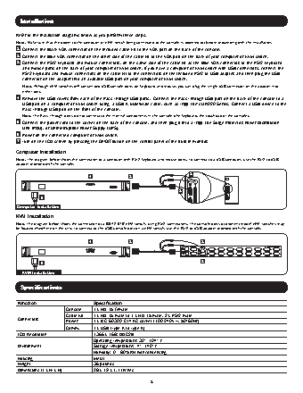
Installation
Refer to the installation diagrams below as you perform these steps.
Note: Make sure that the power to the computer or KVM switch being connected to the console is powered off before proceeding with the installation.
1   Connect the Black VGA connector on the included cable kit to the VGA port on the back of the console.
2   Connect the Blue VGA connector on the other side of the cable kit to the VGA port on the back of your computer or KVM switch.
3   Connect the PS/2 keyboard and mouse connectors, on the same side of the cable kit as the Blue VGA connector, to the PS/2 keyboard
and mouse ports on the back of your computer or KVM switch. If you have a computer or KVM switch with USB connectors, connect the
PS/2 keyboard and mouse connectors on the cable kit to the connectors on the included PS/2 to USB adapter, and then plug the USB
connector on the adapter into an available USB port on your computer or KVM switch.
Note: Although KVM switches will contain two USB console ports for keyboard and mouse, you can plug the single USB connector on the adapter into
either port.
4    Remove the USB covers from each of the Pass-Through USB ports.  Connect the Pass-Through USB port on the back of the console to a
USB port on a computer or KVM switch using  a USB A Male/Male cable, such as Tripp Lite’s UR020-Series. Connect a USB device to the
Pass-Through USB port on the front of the console.
Note: The Pass-Through ports do not connect to the internal components in the console (the keyboard, the touchpad or the console).
5    Connect the power cord to the socket on the back of the console, and then plug it into a Tripp Lite Surge Protector, Power Distribution
Unit (PDU), or Uninterruptible Power Supply (UPS).
6   Power on the connected computer or KVM switch.
7   Turn on the LCD screen by pressing the On/Off button on the control panel of the built-in monitor.
Computer Installation
Note: The diagram below shows the connection of a computer with PS/2 keyboard and mouse ports. To connect to a USB computer, use the PS/2 to USB
adapter provided with the console.
4               1                        3
2
5
Computer Installation
KVM Installation
Note: The diagram below shows the connection of a B042-016 KVM switch, using PS/2 connections. The console ports of different model KVM switches may
be located elsewhere on the unit. To connect to the USB console port on a KVM switch, use the PS/2 to USB adapter provided with the console.
4               1                            3
5                                                                2
KVM Installation
Specifications
Function                       Specification
Console    1 x HD-15 female
Cable Kit  1 x HD-15 male to 1 x HD-15 male, 2 x PS/2 male
Connectors          Power      1 x IEC-60320-C14 AC socket (100-240V~, 50/60Hz)
Comm.      1 x USB (Type A to Type A)
LCD Resolution                 1366 x 768; DDC2B
Operating Temperature: 32°- 104° F
Environment                    Storage Temperature: -4°- 140° F
Humidity: 0 - 80% RH Noncondensing
Housing                        Metal
Weight                         36 pounds
Dimensions (L x W x H)         28 x 19 x 1.7 inches
3