На сайте 123408 инструкций общим размером 499.34 Гб , которые состоят из 6235299 страниц
Фото
Руководство пользователя FELISATTI RF62/2200VE. Основные функции, характеристики и условия эксплуатации изложены на 32 страницах документа в pdf формате.
Доступно к просмотру 30 страниц. Рекомендуем вам скачать файл инструкции, поскольку онлайн просмотр документа может сильно отличаться от оригинала.
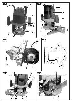
Fig.1                           C       Fig.2
L
N
M
A
G
E
H                             I
F
B
S
J       P
Fig. 3                                       Fig. 4
T
Q        U
Fig. 5      H                           Fig. 6               R
A
O
O
V     Q       D   K                              V      K
TECHNICAL DATA
Milling machine                                                      RF62/2200VE
Absorbed power              W                                              2200
No load speed               rpm                                       11800-21000
? of milling cutter attachment   mm                                          12
Lengthwise travel           mm                                             0-67
? maximum of milling cutter   mm                                             60
Machine weight (without accessories)   kg                                   5.6
Total machine height        mm                                              305
The instructions contained in this manual must be strictly   ? WARNING! The dust produced when milling asbestos
followed, it should  be carefully read  and kept close  at   and/or  silica stone  materials is  dangerous to health.
hand  to use when carrying out maintenance on the   Follow the insurance company’s safety  instructions
indicated parts.                          regarding the responsibility of employees.
If the machine is used carefully and normal maintenance   ? For your personal safety, always connect the machine
is carried out, it will work for a long time.   to a mains supply by a differential and thermal cut-out
The functions and use of the tool you have bought shall   switch, in accordance with regulations on low-voltage
be only those described in this manual. Any other use   wiring sitemaps.
of the tool is strictly forbidden.      ? Do not perforate the machine casing, as this would
destroy the protective insulation (use adhesive labels).
ILUSTRATIONS                            ? Always unplug the machine before doing any work on it.
DESCRIPTION (See figures)               ? Always  stop the machine by switching it off, not by
unplugging it.
A  ON/OFF switch lever (Fig.2 and Fig.5)   ? WARNING! Before each  use, inspect  the plug  and
B  Spindle lock of shaft (Fig.1)          lead. Should they need replacing, have this done by an
C  Depth adjustment handle (Fig.1)        official service centre. Only plug the machine in when it
D  Clip fixing nut (Fig.5)                is switched off.
E  Depth stop (Fig.1)                   ? Always keep the  lead out of  the machine’s  working
F   Stepped stop (Fig.1)                  area.
G  Locking button (Fig.1)               ? Only plug the machine in when it is switched off.
H  Fixing lever (Fig.2 and Fig.5)       ? Do not allow the machine to get wet, nor should it be
I   Side stop (Fig.2)                     used in wet environments.
J   Transparent frontal protection (Fig.1)   ? When using the machine, always wear safety goggles,
K  Dust suction adapter (Fig.5 and Fig.6)   gloves and non-slip footwear, and it is advisable to
wear ear protection.
L   Speed adjustment (Fig.2)            ? Check for correct piece fixing before commencing any
M  Depth adjustment scale (Fig.1)         operation.
N  Speed adjustment scale (Fig.2)       ? Only milling heads with acceptable revolutions that are
O  Grips (Fig.1 and Fig. 2)               at least the same as the maximum off-load revolutions
P  Base plate (Fig.1)                     of the machine should be used.
Q  Sliding plate (Fig.3 and Fig.5)      ? The milling head shaft diameter should match the
R  Wing screw for dust suction adapter (Fig.6)   inside diameter of the tool-holder (locking clip).
S  Strip stop (Fig.2)                   ? It should be ensured that the milling head is firmly held
T   Parallel stop fine adjustment (Fig.3)   in place before the machine is operated.
U  Copier bushing (Fig.3)               ? The clip-carrier shaft support lever must only be oper-
V  Wing screw (Fig.5 and Fig.6)           ated when the machine is stopped.
? The milling head should only be brought into contact
EQUIPMENT                                 with the work-piece after it has been switched on.
- Side stop                             ? The machine must be firmly held by the grips. Other-
- Clip, ?1/2” and ?1/4”                   wise the recoil produced could cause the machine to
- Fixed spanner, 22 mm and 8 mm           work imprecisely or even dangerously.
- Transparent guard                     ? Hold the machine firmly in both hands and in a stable
- Dust suction adapter                    position.
- Copier bushing                        ? During use, it should be ensured that the milling head
- Operating instructions                  is in the centre of the copy bushing in order to prevent
- Safety instructions                     any personal injury or damages to the work-piece.
- Warranty                              ? The milling  machine must  never be  used on  metal
objects, such as nails and screws.
SAFETY INSTRUCTIONS                     ? Hand must be kept clear of the milling machine while it
? See “Safety Instructions” enclosed manual, supplied   is operating.
together with this instruction manual.
? The cutting depth must never be adjusted with the motor   MILLING HEAD SELECTION AND INSTALLATION
running.  A mistake  in this  time could  lead to personal   1.1. Milling head selection
injury and/or damage to the milling head or work-piece.   Depending on the materials to be worked, the following
? The operator should remain alert and keep the milling   milling head qualities may be selected:
head apart from all objects during operation.
? When  the milling operation has been completed,   ? High-performance, fast-cutting steel milling heads
locking lever should be operated so that the machine   (HSS): suitable for soft materials, such as soft woods
returns to its upper starting position.   and plastic.
? The motor must be allowed to come to completely stop   ? Milling heads with hard metal blades (HM): suitable
before being put to one side between uses.   hard and abrasive materials, such as hard woods and
? The milling heads should be protected from impacts   aluminum.
and knocks.                            WARNING! The milling heads that are employed must
? The milling heads should not be touched after use   be officially approved in accordance with the maximum
revolutions defined for the respective tools. The milling
because they could cause serious burns.
head shaft diameter should match the inside diameter of
BRIEF DESCRIPTION                       the tool-holder (locking clip).
This machine is designed for use with rotary milling heads   1.2. Milling head installation
for milling slots, edges,  profiles and rough-edged  holes,   WARNING! The mains cable must be removed from the
from a firm base, in wood, synthetic and light construction   socket before any adjustments are made to the machine.
materials, and for milling operation with a copier.   It is recommended that protective gloves be worn when
By employing the correct milling heads and using slow   installing or removing milling heads.
speeds, non-ferrous metals may also be milled.   - To install the milling head, press the spindle lock  of
shaft B until it coincides with the shaft planes.
BEFORE USING THIS TOOL
- A 22-mm spanner should be used to loosen clip fixing
Make sure the mains voltage is correct: it must be the   nut D in an anticlockwise direction.
same as that on the specification label. Machines with   - Insert the milling head so that the shaft enters the clip
230-V can also be connected to a 220-V mains supply.   by a minimum of 20 mm (shaft length).
The machine  is put  into operation  using the  lever  A,   - Tighten  the clip fixing nut  D with the spanner and
pressing it upwards (I-ON) will start the machine. Press-  release the clip-carrier shaft support lever B.
ing it towards the base (0-OFF) will stop it.   PRECAUTION: Do not tighten clip fixing nut D without a
Speed adjustments. Constant electronic performance   milling head inserted into the clip.
The  control electronics allow  continuous pre-setting of   ADJUSTING MILLING OPERATION DEPTH
the revolutions and impact frequency to adapt the ma-
chine  to the type of material  to be worked on. Adjust-  WARNING! The milling operation depth adjustment
ment  is made  using the speed  adjustment switch  L,   must only be performed with the machine switched off.
which has 6 positions to regulate the speed.   The milling operation depth may be adjusted according
The  higher the number, the  greater the speed and   to the work to be carried out.
impact energy. The  range of settings  from “1”  (low   The  machine is fitted  with a depth  stop  E, the upper
power) to “6” (full power)  makes the tool very  flexible   surface of which is used in conjunction with the gradu-
and adaptable to different applications.   ated scale M fine control of the milling operation depth.
The constant speed control maintains the pre-set num-  For deep cutting operations,  it is recommended  that
ber of revolutions and impact frequency.   several passes be made, with a reduced chip thickness.
Check the speed adjustment  label  N for the  desired   Operate the fixing lever  H and slowly push the  upper
working speed.                          section of the machine against the depth stop E. Lock
the machine by releasing the fixing lever H.
Revolutions table
Material           ? milling   Revolution   Pressing locking button G will unlock the depth stop E,
head      stages   providing a simple method of stop adjustment.
Hard wood (beech)   4-10 mm     5-6     Fixing lever  H should be pressed to immobilize the
12-20 mm     3-4     machine at a determined working height.
22-40 mm     1-2     To prevent running off-load, rotate the depth adjustment
Soft wood (pine)   4-10 mm      5-6     handle C until the desired return distance is obtained.
12-20 mm     3-6     With the stepped stop  F  it is possible to perform  the
22-40 mm     1-3     milling  operation in  three stages. To  start, adjust the
Plywood boards     4-10 mm      3-6     milling depth  to the  lowest position  of stepped  stop  F.
12-20 mm     2-4     Then  the milling  operation can  be carried  out at the
22-40 mm     1-3
Synthetic materials   4-15 mm   2-3     higher positions.
16-40 mm     1-2     PRECAUTION:  For large diameter  cuts, it is recom-
Aluminum           4-15 mm      1-2     mended  that the  depth is set  to minimum  and to con-
16-40 mm     1       tinue cutting in stages.
The values in this table are for guideline purposes only.   When commencing the work, the milling head should be
The required revolutions will depend on the material and   slowly entered until the  desired depth is obtained  and
working conditions. It  is recommended  that these  be   then allowed to advance, always supporting the machine
established by carrying out tests with the machine.   with two hands.