На сайте 123429 инструкций общим размером 499.45 Гб , которые состоят из 6236153 страниц
Фото


Руководство пользователя FELISATTI RF62/1500VE. Основные функции, характеристики и условия эксплуатации изложены на 33 страницах документа в pdf формате.
Доступно к просмотру 29 страниц. Рекомендуем вам скачать файл инструкции, поскольку онлайн просмотр документа может сильно отличаться от оригинала.
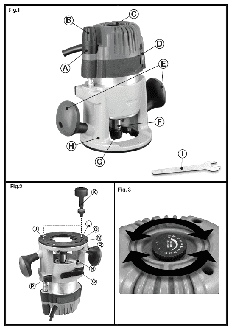
TECHNICAL DATA
Milling machine                                                      RF62/1500VE
Absorbed power              W                                              1500
No load speed               rpm                                       12000-23000
? of milling cutter attachment   mm                                          12
? maximum of milling cutter   mm                                             60
Machine weight (without accessories)   kg                                  2.450
The instructions contained in this manual must be strictly   ? Always unplug the machine before doing any work on it.
followed, it should  be carefully read  and kept close  at   ? Always  stop the machine by switching it off, not by
hand  to use when carrying out maintenance on the   unplugging it.
indicated parts.                        ? WARNING! Before each  use, inspect  the plug  and
If the machine is used carefully and normal maintenance   lead. Should they need replacing, have this done by an
is carried out, it will work for a long time.   official service centre. Only plug the machine in when it
The functions and use of the tool you have bought shall   is switched off.
be only those described in this manual. Any other use   ? Always keep the  lead out of  the machine’s  working
of the tool is strictly forbidden.        area.
? Only plug the machine in when it is switched off.
ILUSTRATIONS                            ? Do not allow the machine to get wet, nor should it be
DESCRIPTION (See figures)                 used in wet environments.
A  Micro-adjustment disc (Fig.1)        ? When using the machine, always wear safety goggles,
B  Micro-adjustment knob (Fig.1)          gloves and non-slip footwear, and it is advisable to
wear ear protection.
C  Speed adjustment (Fig.1)             ? Check for correct piece fixing before commencing any
D  ON/OFF switch (Fig.1)                  operation.
E Grips (Fig.1)                         ? Only milling heads with acceptable revolutions that are
F   Clip-carrier shaft (Fig.1)            at least the same as the maximum off-load revolutions
G  Clip fixing nut (Fig.1)                of the machine should be used.
H  Fixed base (Fig.1)                   ? The milling head shaft diameter should match the
I   22 mm spanner (Fig.1)                 inside diameter of the tool-holder (locking clip).
J   Access adjustment over the table height (Fig.2)   ? It should be ensured that the milling head is firmly held
K  Depth adjustment handle (Fig.2)        in place before the machine is operated.
L   Unscrew the access base on the table (Fig.2)   ? The clip-carrier shaft support lever must only be oper-
M  Base plate (Fig.2)                     ated when the machine is stopped.
N  Spindle lock of shaft (Fig.2)        ? The milling head should only be brought into contact
with the work-piece after it has been switched on.
O  Fixing lever (Fig.2)
P  Locking button (Fig.2)               ? The machine must be firmly held by the grips. Other-
wise the recoil produced could cause the machine to
Q  Access to the blocking of the rotation axis (Fig.2)   work imprecisely or even dangerously.
R  Locking lever (Fig.2)                ? Hold the machine firmly in both hands and in a stable
S  Copier bushing (Fig.18) (optional accessory)   position.
? During use, it should be ensured that the milling head
EQUIPMENT
is in the centre of the copy bushing in order to prevent
- Clip, ?1/2” and ?1/4”                   any personal injury or damages to the work-piece.
- Fixed spanner, 22 mm                  ? The milling  machine must  never be  used on  metal
- Operating instructions                  objects, such as nails and screws.
- Safety instructions                   ? Hand must be kept clear of the milling machine while it
- Warranty                                is operating.
SAFETY INSTRUCTIONS                     ? The cutting  depth must  never be  adjusted with  the
motor  running. A  mistake in  this time  could lead to
? See “Safety instructions” enclosed manual, supplied   personal injury and/or  damage to the  milling head  or
together with this instruction manual.   work-piece.
? WARNING! The dust produced when milling asbestos   ? The operator should remain alert and keep the milling
and/or  silica stone  materials is  dangerous to health.   head apart from all objects during operation.
Follow the insurance company’s safety  instructions   ? When  the milling operation has been completed,
regarding the responsibility of employees.   locking lever should be operated so that the machine
? For your personal safety, always connect the machine   returns to its upper starting position.
to a mains supply by a differential and thermal cut-out   ? The motor must be allowed to come to completely stop
switch, in accordance with regulations on low-voltage   before being put to one side between uses.
wiring sitemaps.                       ? The milling heads should be protected from impacts
? Do not perforate the machine casing, as this would   and knocks.
destroy the protective insulation (use adhesive labels).
? The milling heads should not be touched after use   e)  Insert the milling head so that the shaft enters the
because they could cause serious burns.    clip by a minimum of 20 mm (shaft length). Tighten
the clip fixing nut G with the spanner and release
BRIEF DESCRIPTION                           the clip-carrier shaft support lever N (Fig.6).
This machine is designed for use with rotary milling heads   f)   Rotate locking lever R until it disengages the spin-
for milling slots, edges,  profiles and rough-edged  holes,   dle lock N. Press the locking button P and slide the
from a firm base, in wood, synthetic and light construction   router motor out of the base until the router bit is
materials, and for milling operation with a copier.   back below the surface of the router base  and
By employing the correct milling heads and using slow   close base clamp O.
speeds, non-ferrous metals may also be milled.   g)  Before operating the router, follow directions in the
section in this  manual titled  "Adjusting Depth  of
BEFORE USING THIS TOOL                      Cut" to properly set your depth of cut.
Make sure the mains voltage is correct: it must be the   h)  To remove a router bit from the collet, follow steps
same as that on the specification label. Machines with   b,c, and d and then remove the router bit.
230-V can also be connected to a 220-V mains supply.
Start the machine  by turning the  switch to position  1   OPTION 2 – Through The Base Bit Changes
("on"). To switch off, do the same in reverse.   a)  Unlock the base by inserting the height adjustment
wrench K into the above table base clamp access
Speed adjustments. Constant electronic performance   hole L and turn counter clockwise until the wrench
The control electronics allow continuous pre-setting of the   stops turning (Fig.7).
revolutions and impact frequency to adapt the machine to   b)  Insert the depth adjustment wrench into the above
the type of material to be worked on. The adjustment is   table height adjustment  access hole  J and  rotate
carried out through the velocity regulator C (Fig.3).   counter clockwise until the  collet  G extends  fully
The constant speed control maintains the pre-set num-  through the base (Fig.8).
ber of revolutions and impact frequency.   c)  Insert  the depth adjustment wrench into the
If the motor velocity diminishes during work, it is possi-  spindle lock access hole Q and rotate clockwise
ble that you are exercising excessive pressure on the   until it stops. Rotate spindle F until spindle lock
material  to be worked  on. This may  harm the motor   pin N engages. When the spindle lock pin is cor-
through overheating.                        rectly engaged, you will not be able to rotate the
Reducing the depth of the cut and passing over it more   spindle (Fig.9).
times may reduce overheating.            d)  A 22-mm spanner should be used to loosen  clip
fixing nut G in an anticlockwise direction (Fig.10).
MILLING HEAD SELECTION AND INSTALLATION
e)  Insert  the bit  into the  collet and  with the 22mm
1.1. Milling head selection                 wrench rotate the collet nut clockwise to tighten the
Depending on the materials to be worked, the following   collet (Fig.11).
milling head qualities may be selected:   f)   Insert the depth adjustment wrench into the spindle
? High-performance, fast-cutting steel milling heads   lock access  hole  Q  and rotate counter clockwise
(HSS): suitable for soft materials, such as soft woods   until it stops turning (Fig.12).
and plastic.                            g)  Insert depth adjustment wrench into the  above
? Milling heads with  hard metal  blades (HM): suit-  table  height adjustment access  hole  J and turn
able  hard and abrasive  materials, such as hard   clockwise to lower the router bit. Lock the base
woods and aluminum.                        by inserting the height adjustment wrench  into
WARNING! The milling heads that are employed must   the  above table  base clamp access  hole  L and
be officially approved in accordance with the maximum   turn the wrench clockwise until the wrench stops
revolutions defined for the respective tools. The milling   turning (Fig.13).
head shaft diameter should match the inside diameter of   h)  Before operating the router, follow directions in the
the tool-holder (locking clip).             section  in this manual  titled “Adjusting Depth of
1.2. Assembly of the milling machine (2 options)   Cut” to properly set your depth of cut.
WARNING! The mains cable must be removed from the   PRECAUTION: Do not tighten clip fixing nut G without a
socket before any adjustments are made to the machine.   milling head inserted into the clip.
It is recommended that protective gloves be worn when   Failure to release the locking button N or to remove the
installing or removing milling heads.   22-mm spanner before  operating this  power tool  could
OPTION 1 – Hand Held Use                result in injury or damage to the tool.
a)  Opening the  fixing lever  O of  the milling machine   ADJUSTING MILLING OPERATION DEPTH
(Fig.2).
b)  Press the locking button P and push the handles of   WARNING! The milling operation depth adjustment
the milling machine downwards until nut G protrudes   must only be performed with the machine switched off.
over the base. Turn the locking lever R until it fits in   The milling operation depth may be adjusted according
with the blocking of the rotating axis N (Fig.4).   to the work to be carried out.
c)  To assemble the milling machine, press the block-  For deep cutting operations,  it is recommended  that
ing button of the  clip-holder shaft  N matching  up   several passes be made, with a reduced chip thickness.
the pivot with the axis groove F.
d)  A 22-mm spanner should be used to loosen  clip   OPTION 1 – Hand Held Use
fixing nut G in an anticlockwise direction (Fig.5).   a)  Loosen the fixing lever O (Fig.2).
b) Turn the micro adjusting knob until the bit contacts plate Y, put the copier brushing with the plain side the work surface making sure that the router is towards the milling machine and tighten screws Z in level and flat (Fig.14). order to fix the copier brushing. c) Turn the micro adjustment knob B clockwise to the WARNING! It is essential to ensure correct installation desired depth. (one complete rotation varies the bit position. depth by 1/8"). d) Lock the base clamp O prior to operation. The base plate L has been centred at the factory, how- ever, if the base plate has been removed and remounted OPTION 2 – Through The Base Bit Changes some adjustment may be necessary to centre the tem- a) Unlock the base by inserting the height adjustment plate guides to the router bit. wrench K into the above table base clamp access To adjust, loosen the four base plate screws that secure hole L and rotate counter clockwise until the the base plate to the router, reposition the base plate wrench stops turning (Fig.15). and tighten the screws. b) Insert the depth adjustment wrench into the above table height adjustment access hole J. Turn the 1.3. Milling straight or profiled edges wrench counter clockwise to raise the bit and The operating machine should be brought into contact clockwise to lower the bit (Fig.16). with the work-piece from the side, until the milling head c) Once the bit is set at the desired depth of cut, lock guide shaft or ball bearing is seated against the edge of the base by inserting the height adjustment wrench the work piece. The machine must be guided with both into the above table base clamp access hole L and hands, always perpendicular to the surface, along the turn the wrench clockwise until the wrench stops entire length of the work-piece edge. Excessive applied turning (Fig.17). pressure could damage the work-piece edge. PRECAUTION: For large diameter cuts, it is recom- mended that the depth is set to minimum and to con- DUST EXTRACTION tinue cutting in stages. WARNING! Always make sure that the tool is switched When commencing the work, the milling head should be off and unplugged before fitting or removing any dust slowly entered until the desired depth is obtained and extraction device. then allowed to advance, always supporting the machine with two hands. Dust extraction keeps the workplace clean, prevents dust build-up in the air and facilitates waste elimination. OPERATING INSTRUCTIONS. These milling machines are fitted with adapter, which PRECAUTION: The machine should always be un- can be coupled to a universal vacuum aspirator or other plugged before making any adjustments to the machine. dust suction device. Fix the working pieces well before proceeding with any CAUTION: A suction extractor should always be used type of operation. that has been designed in accordance with the applica- WARNING! Sanding should always be carried out in ble directives in relation to dust emission when milling the contrary direction of the rotating direction of the wood. The flexible hoses of conventional vacuum clean- milling machine; in the case of external border treat- ers fit directly onto the dust extraction nozzle. ments, move the milling machine towards the left and from the left to the right. Advancing the machine in Installing the dust suction adapter the opposite direction could cause it to rebound and PRECAUTION: Before mounting the dust extraction lead to an accident. adaptor, open the fixing lever O so that the upper part of WARNING! Avoid inverse cuts (moving the milling the apparatus will ascend to a superior position. machine towards the right with the rotation of the milling In order to install the dust extraction adapter, it should head). The inverse cut increases the possibility the be inserted in the opening on the base plate H (until it milling machine's loss of control and there is the risk of fits firmly into place), and then fixed using the thumb- personal harm. screws, which are located on both sides of the adapter. 1.1. Milling In order to maintain optimum chip extraction, the suction 1. The milling depth should be adjusted in accordance adapter should be periodically cleaned. with the previous description. The aspirator should be suitable for the material being 2. Switch on and place the machine over the work worked. piece, firmly held in place. A special aspirator must be employed in those cases 3. Carry out the milling operation with a uniform ad- where dry harmful or carcinogenic dust is produced. vancing movement. 4. On completing the milling operation, push the upper In situations where prolonged wood operations are performed or machines are used industrially with materi- section of the machine upwards and switch it off. als that produce dust that is harmful to health, the ma- 1.2. Milling with the copier bushing chine must be connected to a suitable external aspira- The copier brushing (optional) S allows to sand the tion device. outline of the work-piece in accordance with a pattern or a template. MOUNTING ONTO A MILLING MACHINE TABLE Installing the copier bushing (Fig.18) These milling machines can also be mounted onto a In order to use the copier brushing (optional) S milling machine table. In order to mount the milling should be mounted on the base plate using the sup- machine, please follow the instructions of the milling plied screws Z. Remove the screws from the base machine table.