На сайте 123377 инструкций общим размером 499.27 Гб , которые состоят из 6233966 страниц
Фото
Руководство пользователя FELISATTI RF100/710. Основные функции, характеристики и условия эксплуатации изложены на 25 страницах документа в pdf формате.
Доступно к просмотру 23 страницы. Рекомендуем вам скачать файл инструкции, поскольку онлайн просмотр документа может сильно отличаться от оригинала.
BISCUIT JOINER
ENGALLETADORA
ASSEMBLEUSE
INTESTATRICE
FLACHDUBELFRASE
SERRA DE CREMALHEIRA
ЛАМЕЛЬНЫЙ ФРЕЗЕР
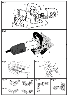
TECHNICAL DATA
Biscuit joiner                                                         RF100/710
Input power                W                                                710
No-load speed              rpm                                             9000
Saw blade diameter         mm                                               100
Working shaft thread       mm                                            M10x1.5
Set width                  mm                                               3.5
Saw blade hole diameter    mm                                                22
Maximum milling depth      mm                                                20
Approx. weight (without accessories)   Kg.                                  2.8
The instructions contained in this manual must be strictly   mal cutout switch, in accordance with regulations  on
followed, it should  be carefully read  and kept close  at   low-voltage wiring sitemaps.
hand  to use when carrying out maintenance on the   ? Do not pierce the motor housing as this could damage
indicated parts.                          the insulation (use adhesive labels).
If the tool is used with care and normal maintenance is   ? Always unplug  the machine  before carrying  out
carried out, it will work well for a long time.   work on it.
The functions and use of the tool you have bought shall   ? Always  stop the machine by switching it off, not by
be only those described in this manual. Any other use   unplugging it.
of the tool is strictly forbidden.      ? Always keep the mains lead clear of the working range
of the machine.
ILLUSTRATIONS                           ? Only plug the machine in when it is switched off.
DESCRIPTION (See figures)               ? Check that the work piece is correctly secured before
A  Saw blade (Fig.5)                      commencing any job.
C  Adjustable stop (Fig.1)              ? Never use the  machine without  the guard.  Keep
D  Saw blade securing nut (Fig.5)         guards in place.
E  Switch control (Fig.1)               ? Beware of shavings that fly off.
F   Support base/saw blade protection (Fig.1)   ? The cutting path must be free from obstacles in both
upper and lower sections.
G  Depth adjustment divisions (Fig.2)   ? The tool must not be wet or be operated in a  damp
H  Locking lever (Fig.1)                  environment.
I  Springs (Fig.4)                      ? When  working with the  machine, protective goggles,
J   Spring hooks (Fig.4)                  gloves, and a  facemask when  necessary to  protect
K  Saw blade replacement blocking button (Fig.1)   from  dust, and non-slip safety footwear must always
L   Saw blade seating billet (Fig.5 side opposite the saw   be worn, and ear protection is also recommended.
blade)                               ? This machine must  not be  employed on  material
M  Back cover (Fig.1)                     containing asbestos.
N  Dust extraction nozzle (Fig.2)       ? Make sure  the vents  are free  when working  with
O  Moveable square (Fig.1)                dust.  If they  require cleaning, first  unplug the ma-
P  Blade exit central marking (Fig.1)     chine, do not insert metal objects and avoid damag-
ing internal parts.
R  Pin wrench (Fig.5)                   ? Hands or the body must never be positioned in front of
S  Auxiliary grip (Fig.1)                 the saw blade while the machine is operating.
T   Depth adjustment screw (Fig.2)      ? When the  job is  complete, the  machine must  be
U  Rack and pinion knob (Fig.1)           switched off and the saw blade allowed to come to a
complete stop.
EQUIPMENT
? The support base protection must always be used. The
- 1 saw blade                             actual  support base  protects the  user from possible
- 1 pin spanner                           flying debris in  the case  of a broken  saw blade  and
- 1 fixed spanner                         also from accidental contact with the saw blade.
- 1 spring extraction hook              ? When a saw blade is installed, the interior disc must be
- 1 bag to collect shavings               adjusted in the shaft orifice.
- Operating instructions                ? After switching the biscuit joiner off, no attempt must
- Safety instructions                     be made to stop the saw blade by using pressure.
- Warranty
? Do not use  broken or  cracked blades.  Use only  well
SAFETY INSTRUCTIONS                       sharpened blades in good condition. Change broken or
bent blades immediately.
? Please  see  “Safety Instructions” manual, supplied   ? Only use saw blades conforming to the specifications
with this instruction manual.            contaned in these operating instructions.
? For your personal safety, always connect the machine   ? Check that  the saw  blade is  secure and  turns in  the
to a mains supply protected by a differential and ther-  right direction.
? Unplug the machine from the mains before changing   6. A small amount of lubricant should be applied to the
the blade, making adjustments  or carrying out  any   hole in base F, which must then be reassembled in
other maintenance work on it.             the reverse order in which it was removed.
? Using the manufacturer's information, ensure that the   CARE MUST BE TAKEN to ensure that the saw blade
diameter, thickness  and other  characteristics of  the   cutting  direction coincides with  the machine’s cutting
blade are suitable for the tool and also that the blade is   direction as indicated by an arrow on the head.
suitable for the speed of the shaft.
? Before operating the tool, inspect for and remove all   SETTINGS
nails or other  foreign material  that might  be in  the   1. Cutting depth setting
work piece.                            The cutting depth is preset at the factory.
? Hands must never be placed under the work pieces   The machine is fitted with an adjusted depth regulator G,
while the blade is rotating.           with three cutting positions to cover the three standard
? The tool must never be left unattended while it  is   flat sheet sizes.
operating.                             Rotate regulator G until the pointer indicates the requi-
? CARE MUST BE TAKEN to ensure that the saw blade   red size marked on the regulator. Regulator G includes
cutting direction coincides with the machine’s cutting   the various depth divisions to prevent this from rotating
direction as indicated by an arrow on the head.   during operation. The following table should be consul-
? Under no circumstance should the machine be put into   ted in order to establish the correspondence  between
operation with the saw blade supported on the board.   the sizes marked on regulator G and the sheet sizes:
? A protective face mask must be employed in any work   Position  Depth  Sheets
producing  harmful dust.  Material containing asbestos   00   8 mm    n? 0
must not be worked.                          10         10 mm         n? 10
BRIEF DESCRIPTION                             20         14 mm         n? 20
This tool is a biscuit joiner for joints using flat nails and is   2. Slot position
designed to produce various types of mitres.   In boards with a thickness exceeding 25mm, it is recom-
mended that two assembly sheets be placed in parallel.
BEFORE USING THIS TOOL                  Moveable square  O can  be moved  up and  down in
Before  using the tool,  make sure the  mains voltage is   order to adjust the saw blade in relation to the upper
correct: it must be the same as that on the specification   part of the  work piece.  To adjust  the height,  loosen
label. Machines with 230V can also be connected to a   locking lever H and move it upwards or downwards to
220V mains supply.                      the regulation desired on the regulation scale and push
Before plugging in the tool, always make sure the control   locking lever H.
switch E works properly and returns to the OFF position   3. Cutting execution
when released.                          WARNING! Always unplug the machine before carrying
out any work on it.
START UP
Assure yourself that the saw  disc and the knobs  are
WARNING! Only plug in when machine is switched off.   tightened.
The machine is switched on by moving switch to position   Check that the  piece is fixed  to the work  surface
“1” (ON). To switch off, do the same in reverse.   with a clamp.
Connect the tool.
FITTING THE DISC
Align the central mark of the biscuit joiner with the line
WARNING! Always unplug the machine before carrying   drawn on the piece that is going to be worked on.
out any work on it.                     Firmly hold the machine by the auxiliary handle and by
CAUTION: Do not use  bent or cracked blades  or   the  back cover  and connect the  machine putting the
high-speed steel blades. Do not use saw blades that   switch on the ON position and allow for the saw disc to
do not conform to the specifications contained in   reach its maximum velocity.
these instructions.                     With the machine  placed on an  angle over the  piece,
Do not operate blocking button K when the machine   insert the saw disc in the piece until it reaches the bot-
is operating                            tom of the selected depth limit.
1. Unscrew the two screws for saw blade  installa-  Extract the cutting saw disc and turn off the machine.
tion/removal that holds rear cover M in place.   TYPES OF JOINING OPERATIONS
2. Remove springs I from the base using spring extrac-
tion hooks J. Springs I are on wither side of the rear   1. Making corner mitre joints (Fig.7a)
section of base F.                     2. Joining ends (Fig.7b)
3. Now, rear cover M can be removed towards the rear   3. T joints (Fig.7c)
of the machine. This will expose the saw blade.   4. Flat mitre joints (Fig.7d)
4. To remove the saw blade, press blocking button  K
and use the pin spanner to loosen nut D.   DUST EXTRACTION
5. Ensure that the nut and seated billet for the saw   WARNING! Always make sure that the tool is switched
blade are correctly adjusted before re-installing   off and unplugged before fitting or removing any dust
the base.                             extraction device.