На сайте 123408 инструкций общим размером 499.34 Гб , которые состоят из 6235299 страниц
Фото


Руководство пользователя PIONEER GM-X944. Основные функции, характеристики и условия эксплуатации изложены на 6 страницах документа в pdf формате.
Доступно к просмотру 6 страниц. Рекомендуем вам скачать файл инструкции, поскольку онлайн просмотр документа может сильно отличаться от оригинала.
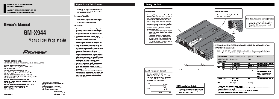
BRIDGEABLE FOUR-CHANNEL Before Using This Product Setting the Unit POWER AMPLIFIER Thank you for purchasing this PIONEER AMPLIFICADOR DE POTENCIA DE product. Before attempting operation, be CUATRO CANALES EN PUENTE sure to read this manual. Gain Control Power Indicator Adjusting the gain controls A and B will The power indicator lights when the In case of trouble help match the output of the car stereo to power is switched on. the Pioneer amplifier. Normally, set the When the unit does not operate properly, gain controls to the “NORMAL” posi- BFC (Beat Frequency Control) Switch contact your dealer or the nearest autho- tion. If the output is low, even when the rized PIONEER Service Station. volume of the car stereo is turned up, If you hear a beat while listening to an Owner’s Manual WARNING turn these controls clockwise. If there is AM broadcast with your car stereo, change the BFC switch using a small distortion when the volume of the car stereo is turned up, turn these controls standard tip screwdriver. • Always use the special red battery and ground counter-clockwise. wires ([RD-223] ?2), which are sold separately. GM-X944 Connect the battery wire directly to the car battery controls for speaker outputs A and B to the • If you only use one input plug, set the gain positive terminal (+) and the ground wire to the same position. car body. • When using with an RCA equipped car • Do not touch the amplifier with wet hands. stereo (standard output of 500 mV), set to Otherwise you may get an electric shock. Also, do the NORMAL position. When using with Manual del Propietario • For traffic safety and to maintain safe driving an RCA equipped Pioneer car stereo with not touch the amplifier when it is wet. max. output of 4 V or more, adjust level to conditions, keep the volume low enough so that match the car stereo output level. you can still hear normal traffic sound. • Check the connections of the power supply and LPF (Low-Pass Filter)/HPF (High-Pass Filter)/BPF (Band-Pass Filter) and speakers if the fuse of the separately sold battery wire or the amplifier fuse blows. Detect the cause LOW/HIGH Select Switch and solve the problem, then replace the fuse with another one of the same size and rating. Set the LPF/HPF/BPF and LOW/HIGH select switch as follows according to the type of • To prevent malfunction of the amplifier and speaker that is connected to the speaker output connector and the car stereo system: speakers, the protective circuit will cut the power supply to the amplifier (sound will stop) when an abnormal condition occurs. In such a case, switch LPF/HPF/BPF Audio frequency range Speaker Remarks the power to the system OFF and check the and LOW/HIGH to be output Type connection of the power supply and speakers. PIONEER CORPORATION Detect the cause and solve the problem. Select Switch 4-1, MEGURO 1-CHOME, MEGURO-KU, TOKYO 153-8654, JAPAN • Contact the dealer if you cannot detect the cause. LPF HIGH * — 3k to 9k Hz Mid Connect a mid range speaker. 1 • To prevent an electric shock or short-circuit PIONEER ELECTRONICS (USA) INC. LOW * — 40 to 120 Hz Subwoofer Connect a subwoofer. 1 during connection and installation, be sure to P.O. Box 1760, Long Beach, California 90801, U.S.A. HPF HIGH * * 3k to 9k Hz — Tweeter* 3 Connect a tweeter. 2 1 TEL: (800) 421-1404 disconnect the negative (–) terminal of the battery beforehand. 1 PIONEER ELECTRONIC (EUROPE) N.V. LOW * 40 to 120 Hz — Full range Use if you want to cut the • Confirm that no parts are behind the panel when Cut Off Frequency Control Haven 1087 Keetberglaan 1, 9120 Melsele, Belgium drilling a hole for installation of the amplifier. Be very low frequency range* 1 TEL: (0) 3/570.05.11 because it is not necessary sure to protect all cables and important equipment Combining LPF/HPF/BPF and PIONEER ELECTRONICS AUSTRALIA PTY. LTD. such as fuel lines, brake lines and the electrical LOW/HIGH select switch settings lets for the speakers you are 178-184 Boundary Road, Braeside, Victoria 3195, Australia wiring from damage. you select between cut off frequencies using. TEL: (03) 9586-6300 1 from 40 to 120 Hz and 3k to 9k Hz. BPF (for CH A)* 4 * 40 to 120 Hz — Mid Connect a mid range speaker. PIONEER ELECTRONICS OF CANADA, INC. (Example: LPF and HIGH) — 3k to 9k Hz 300 Allstate Parkway, Markham, Ontario L3R 0P2, Canada Published by Pioneer Corporation. TEL: (905) 479-4411 OFF Full range Full range Copyright © 2000 by Pioneer Corporation. (dB) PIONEER ELECTRONICS DE MEXICO, S.A. de C.V. All rights reserved. (3 kHz) (9 kHz) San Lorenzo Num 1009 3er piso Desp. 302 Publicado por Pioneer Corporation. RCA Input Select Switch * See the “Cut Off Frequency Control” section. 1 Col. Del Valle, Mexico D.F. C.P. 03100 Copyright © 2000 Pioneer Corporation. –3 * With CH A, even if the setting is HPF-HIGH, you can only select the same cut off frequency as 2 TEL: 5-688-52-90 Todos los derechos reservados. Level For two-channel input, slide this switch with HPF-LOW (40 to 120 Hz). to the left. For four-channel input, slide * 3 If you connect the tweeter directly, you must set the CH B to HPF-HIGH. Printed in U.S.A. 4 Impreso en los EE.UU. Frequency (Hz) this switch to the right. * Be sure to set the LOW/HIGH select switch to HIGH. <00B00F0R01>ES
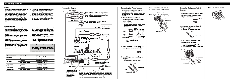
Connecting the Unit
CAUTION                                                                             Connection Diagram                                                                  Connecting the Power Terminal        4. Connect the wires to the terminal.          Connecting the Speaker Output        4. Push on the terminal cover.
• Disconnect the negative (–) terminal of the battery  • Make sure that wires will not interfere with mov-                                                                                                      • Fix the wires securely with the terminal  Terminals
to avoid the risk of short-circuit and damage to  ing parts of the vehicle, such as the gearshift,  Fuse (30 A) ?2                                                    • Always use the special red battery and ground  screws.
the unit.                            handbrake or seat sliding mechanism.          Grommet                        Special red battery wire [RD-223] (sold separately).  wires ([RD-223] ?2), which are sold separately.
• Secure the wiring with cable clamps or adhesive  • Do not shorten any wires. Otherwise the protec-                After making all other connections at the amplifier,  Connect the battery wire directly to the car battery  GND terminal                1. Expose the end of the speaker wires
tape. To protect the wiring, wrap adhesive tape  tion circuit may fail to work when it should.                    connect the battery wire terminal of the amplifier to  positive terminal (+) and the ground wire to the  Power terminal  System remote
around it where they lie against metal parts.  • Never feed power to other equipment by cutting                   the positive (+) terminal of the battery.            car body.                                                control terminal            by about 10 mm and twist using
• Do not route wires where they will get hot, for  the insulation of the power supply wire to tap                                                                                                                                                             nippers or a cutter.
example where the heater will blow over them. If  from the wire. The current capacity of the wire                                                                     1. Pass the battery wire from the                              System remote                                    Twist
the insulation heats up, it may become damaged,  will be exceeded, causing overheating.                                                                                  engine compartment to the interior                          control wire
resulting in a short-circuit through the vehicle                                             Fuse (30 A) ?2       Ground wire (black) [RD-223] (sold separately).        of the vehicle.
body.                                                                                                             Connect to metal body or chassis.                                                                                                                           10 mm
• After making all other connections to the                  Ground wire
amplifier, connect the battery wire terminal of
the amplifier to the positive (+) terminal of
To prevent damage                                                                                                                                                           the battery.                                                                    2. Attach lugs to speaker wire ends.
RCA input  Amplifier with
• Do not ground the speaker wire directly or con-  • Speakers to be connected to the amplifier should                                        RCA input jacks                              Engine                                                              Lugs not supplied.
nect a negative (–) lead wire for several speakers.  conform with the standards listed below. If they     Connecting wires with RCA pin                                        Fuse (30 A)  compart-  Interior of                                           • Use pliers, etc., to crimp lugs to wires.
• This unit is for vehicles with a 12-volt battery and  do not conform, they may catch fire, emit smoke     plugs (sold separately).                                                      ment    the vehicle
negative grounding. Before installing it in a recre-  or become damaged. The speaker impedance must                                                                                                                     Battery wire                                      Lug
ational vehicle, truck or bus, check the battery  be 1 to 8 ohms. But in case of two-channel and
voltage.                             other bridge connections, the speaker impedance                                                       Car stereo with
• If the car stereo is kept on for a long time while  must be 2 to 8 ohms.                                                                   RCA output jacks                                                                                                                    Speaker wire
the engine is at rest or idling, the battery may go  • Install and route the separately sold battery wire   External Output                                                    Fuse (30 A)     Drill a 14 mm
dead. Turn the car stereo off when the engine is at  as far away as possible from the speaker wires.        For details on how to connect to RCA                       Positive terminal       hole into the
rest or idling.                      Install and route the separately sold battery wire,                    input jacks A and B, see the                                     Insert the O-ring rubber  vehicle body.
• If the system remote control wire of the amplifier  ground wire, speaker wires and the amplifier as         “Connecting the Speakers and Input                               grommet into the vehicle                                                     3. Connect the speaker wires to the
is connected to the power terminal through the  far away as possible from the antenna, antenna              wires” section.                                                  body.
ignition switch (12 V DC), the amplifier will  cable and tuner.                                                                                                                                                                                             speaker output terminals.
always be on when the ignition is on— regardless  • Cords for this product and those for other prod-                                                                                                                                                        • Connect the speaker wires, passing them
of whether the car stereo is on or off. Because of  ucts may be different colors even if they have the                                                                                                                                                        through the terminal cover.
this, the battery could go dead if the engine is at  same function. When connecting this product to  Front side                                                       2. Twist the battery wire, ground wire                                                • Fix the speaker wires securely with the termi-
rest or idle.                        another product, refer to the supplied Installation                                                                                 and system remote control wire.                                                      nal screws.
manuals of both products and connect cords that                                                                                                             Twist                                                     Terminal screw
have the same function.
RCA output jack        RCA input jack B
Speaker Channel     Speaker Type          Power
Subwoofer             Nominal input: Min. 95 W                                                        RCA input jack A                           3. Attach lugs to wire ends. Lugs not                                                                      Terminal cover
Four-channel                                                                                                                                                                                                                                              Speaker
Other than subwoofer  Max. input: Min. 150 W                                                                                                        supplied.                                                                         output terminal
Subwoofer             Nominal input: Min. 330 W                                                                                                     • Use pliers, etc., to crimp lugs to wires.
Two-channel
Other than subwoofer  Max. input: Min. 500 W                                                               Connecting wires with RCA pin                            Lug                                                                   Speaker wire
Three-channel       Subwoofer             Nominal input: Min. 95 W                                              Back side      plugs (sold separately).
Speaker output A    Other than subwoofer  Max. input: Min. 150 W
Fuse (30 A) ?3
Three-channel       Subwoofer             Nominal input: Min. 330 W                                                                                                                          Ground wire
Speaker output B    Other than subwoofer  Max. input: Min. 500 W                                                                                                           Lug
Speaker output terminal  System remote control wire (sold separately)
See the “Connecting the  Connect the male terminal of this wire to the system remote control termi-
Speakers and Input  nal of the car stereo (SYSTEM REMOTE CONTROL). The female termi-  Battery wire
wires” section for  nal can be connected to the auto-antenna relay control terminal. If the car
speaker connection  stereo does not have a system remote control terminal, connect the male
instructions.
terminal to the power terminal through the ignition switch.
Connecting the Unit Installation Specifications Connecting the Speakers and Input wires Two-channel mode (stereo) CAUTION Example of installation on the floor Power source ............................................................................................................ 14.4 V DC (10.8 — 15.1 V allowable) • Do not install in: mat or on the chassis Grounding system ............................................................................................................................................ Negative type The speaker output mode can be four-channel, three-channel (stereo + —Places where it could injure the driver or pas- Current consumption ........................................................................................................ 43.7 A (at continuous power, 4 W) mono) or two-channel (stereo, mono). Connect the speaker leads to suit the RCA input jack A RCA Input Select Switch sengers if the vehicle stops suddenly. Average current drawn* ........................................................................................................ 14.5 A (4 W for four channels) mode according to the figures shown below. Slide this switch to the left. —Places where it may interfere with the driver, 1. Place the amplifier where it is to be 26.5 A (4 W for two channels) such as on the floor in front of the driver’s Fuse .......................................................................................................................................................................... 30 A ?3 Four-channel mode seat. installed. Insert the supplied tapping Dimensions ........................................................................................................................ 270 (W) ?60 (H) ?297 (D) mm RCA Input Select Switch Speaker (Right) • Make sure that wires are not caught in the sliding screws (4 ?18 mm) into the screw Weight ...................................................................................................................... 5.4 kg (Leads for wiring not included) For two-channel input, slide this switch to mechanism of the seats, resulting in a short-cir- holes. Push on the screws with a Maximum power output .................................................................................................................... 150 W ?4 / 500 W ?2 the left. For four-channel input, slide this + ? cuit. Continuous power output .......................................................... 75 W ?4 (at 14.4 V, 4 W, 20 — 20,000 Hz, 0.04% THD) RCA input jack B switch to the right. • Confirm that no parts are behind the panel when screwdriver so they make marks 250 W ?2 (at 14.4 V, 4 W, 20 — 20,000 Hz, 0.4% THD) drilling a hole for installation of the amplifier. where the installation holes are to be 125 W ?4 (at 14.4 V, 2 W, 20 — 20,000 Hz, 0.4% THD) RCA input jack A Protect all cables and important equipment such located. Load impedance ............................................................................................................................ 4 W (1 — 8 W allowable) (Right) as fuel lines, brake lines and electrical wiring Connecting wire with RCA (Bridge connection: 2 — 8 W allowable) Speaker out A from damage. plugs (sold separately) 2. Drill 2.5 mm diameter holes at the Frequency response ............................................................................................................ 10 — 50,000 Hz (+0 dB, –1 dB) (Left) • Install tapping screws in such a way that the screw Signal-to-noise ratio ...................................................................................................................... 105 dB (IEC-A network) + +?? From car stereo (RCA output) +? tip does not touch any wire. This is important to point marked, and install the ampli- Distortion ............................................................................................................................................ 0.005% (10 W, 1 kHz) Speaker (Left) prevent wires from being cut by vibration of the fier, either on the carpet or directly Separation ........................................................................................................................................................ 65 dB (1 kHz) car, which can result in fire. to the chassis. • To prevent electric shock, do not install the ampli- Variable crossover network Connecting wires fier in places where it might come in contact with Tapping-screws A CH: LPF-L/LPF-H/HPF-L/BPF with RCA plugs (sold liquids. (4 ?18 mm) B CH: LPF-L/LPF-H/HPF-L/HPF-H separately) • To ensure proper installation, use the supplied Cut off frequency .................................................................................................... Low frequency: 40 — 120 Hz parts in the manner specified. If any parts other High frequency: 3k — 9k Hz Two-channel mode (mono) Cut off slope .......................................................................................................................................... –12 dB/oct +?? + From car stereo (RCA output) than the supplied ones are used, they may damage (Left) If only one input plug is used, such as when internal parts of the amplifier, or they may Maximum input level/impedance .................................................................................... RCA: 6.5 V/22 kW (0.4 — 6.5 V) the car stereo has only one output (RCA out- Speaker out B RCA input jack A become loose causing the amplifier to shut down. Note: put), connect the plug to RCA input jack A, (Right) RCA Input Select Switch • Specifications and the design are subject to possible modification without notice but do not connect a plug to RCA input jack B. Slide this switch to the left. To prevent malfunction • To ensure proper heat dissipation of the amplifier, due to improvements. be sure of the following during installation. Three-channel mode Speaker (Mono) —Allow adequate space above the amplifier for *Average current drawn • The average current drawn is nearly the maximum current drawn by this unit RCA Input Select Switch proper ventilation. Take special care not to Floor mat when an audio signal is input. Use this value when working out total current For two-channel input, slide this switch to + ? block the cooling fan side of the amplifier. or chassis drawn by multiple power amplifiers. the left. For four-channel input, slide this —Do not cover the amplifier with a floor mat or Drill a 2.5 mm diameter hole RCA input jack B switch to the right. carpet. • Do not install the amplifier near a door where it RCA input jack A Connecting wire with RCA may get wet. (Right) • Do not install the amplifier on unstable places plugs (sold separately) Speaker out A such as the spare tire board. (Left) From car stereo (RCA output) ? + • The best location for installation differs with the Speaker (Mono) car model and installation location. Secure the + +?? amplifier at a sufficiently rigid location. • Make temporary connections first and check that the amplifier and the system operate properly. Connecting wires • After installing the amplifier, confirm that the with RCA plugs (sold spare tire, jack and tools can be easily removed. separately) From car stereo (RCA output) ? + Speaker out B If only one input plug is used, such as when (Mono) the car stereo has only one output (RCA out- put), connect the plug to RCA input jack A, but do not connect a plug to RCA input jack B.