На сайте 123408 инструкций общим размером 499.34 Гб , которые состоят из 6235299 страниц
Фото
Руководство пользователя PIONEER DVH-3100UB. Основные функции, характеристики и условия эксплуатации изложены на 6 страницах документа в pdf формате.
Доступно к просмотру 6 страниц. Рекомендуем вам скачать файл инструкции, поскольку онлайн просмотр документа может сильно отличаться от оригинала.
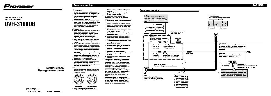
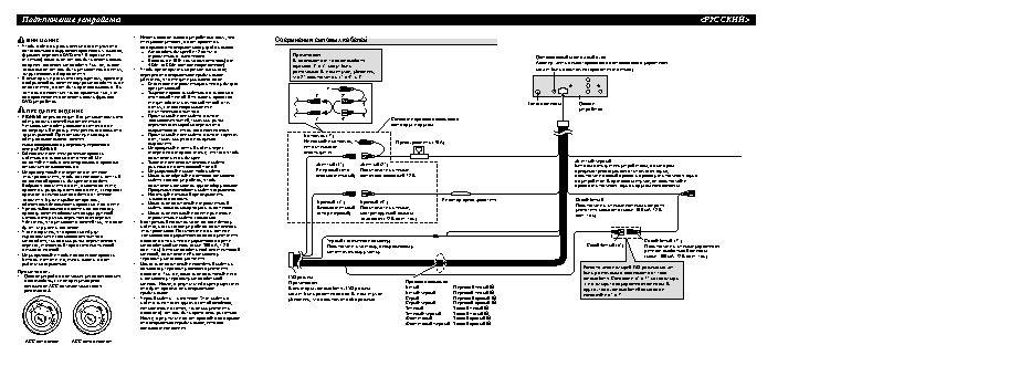
Connecting the Units— Vehicles with a 12-volt battery and negative WARNING grounding. Power cable connection • To avoid the risk of accident and the potential violation of applicable laws, the front DVD or TV — Speakers with 50 W (output value) and 4 ohm (sold separately) feature should never be used to 8 ohm (impedance value). Note: while the vehicle is being driven. Also, Rear • To prevent short-circuit, overheating or Depending on the kind of vehicle, the Wired remote input DVD RDS RECEIVER Displays should not be in a location where it is a malfunction, be sure to follow the directions function of 3* and 5* may be different. In Hard-wired remote control adaptor can be DVD RDS eOeaCOe visible distraction to the driver. below. this case, be sure to connect 2* to 5* and 4* connected (sold separately). • In some countries or states the viewing of images — Disconnect the negative terminal of the battery to 3*. before installation. DVH-3100UB than the driver may be illegal. Where such — Secure the wiring with cable clamps or adhe- 1* on a display inside a vehicle even by persons other sive tape. To protect the wiring, wrap adhesive regulations apply, they must be obeyed and this unit’s DVD features should not be used. tape around them where they lie against metal 3* 2* parts. Antenna jack This product CAUTION — Place all cables away from moving parts, such • PIONEER does not recommend that you install or as gear shift and seat rails. service your display yourself. Installing or 5* 4* Connect leads of the same servicing the product may expose you to risk of — Place all cables away from hot places, such as color to each other. electric shock or other hazards. Refer all near the heater outlet. installation and servicing of your display to — Do not pass the yellow cable through a hole Cap (1*) authorized Pioneer service personnel. into the engine compartment to connect to a Do not remove cap if Fuse (10 A) • Secure all wiring with cable clamps or adhesive battery. this terminal is not in tape. Do not allow any bare wiring to remain — Cover any disconnected cable connectors with use. exposed. insulating tape. • Do not drill a hole into the engine compartment to — Do not shorten any cables. Yellow/black connect the yellow lead of the unit to the vehicle — Never cut the insulation of the power cable of Yellow (3*) Yellow (2*) If you use an equipment with Mute function, wire battery. Engine vibration may eventually cause the this unit in order to share the power to other Back-up (or Connect to the constant this lead to the Audio Mute lead on that equipment. insulation to fail at the point where the wire passes equipment. Current capacity of the cable is accessory) 12 V supply terminal. If not, keep the Audio Mute lead free of any from the passenger compartment into the engine limited. connections. compartment. Take extra care in securing the wire — Use a fuse of the rating prescribed. at this point. — Never wire the speaker negative cable directly • It is extremely dangerous to allow the display lead Red (5*) Red (4*) Fuse resistor Blue/white to ground. to become wound around the steering column or Accessory Connect to terminal controlled Connect to system control terminal of the gearshift. Be sure to install the display in such a — Never band together multiple speaker’s nega- (or back-up) by ignition switch (12 V DC). power amp (max. 300 mA 12 V DC). way that it will not obstruct driving. tive cables. • Make sure that wires will not interfere with • Control signal is output through blue/white cable moving parts of the vehicle, such as the gearshift, when this unit is powered on. Connect it to an parking brake or seat sliding mechanism. external power amp’s system remote control or • Do not shorten any leads. If you do, the protection the vehicle’s auto-antenna relay control terminal Black (chassis ground) Blue/white (7*) circuit may fail to work properly. (max. 300 mA, 12 V DC). If the vehicle is Connect to a clean, paint-free metal location. Blue/white (6*) Connect to auto-antenna relay control equipped with a glass antenna, connect it to the Installation Manual Note: antenna booster power supply terminal. terminal (max. 300 mA 12 V DC). • This unit cannot be installed in a vehicle that • Never connect blue/white cable to external power does not have an ACC (accessory) position on amp’s power terminal. Also, never connect it to The pin position of the ISO connector will differ the ignition switch. the power terminal of the auto antenna. depends on the type of vehicle. Connect 6* and Otherwise, battery drain or malfunction may ISO connector 7* when Pin 5 is an antenna control type. In result. Note: Speaker leads another type of vehicle, never connect 6* and 7*. ACC In some vehicles, the ISO connector White: Front left + OFF ON OFF ON • Black cable is ground. This cable and other product’s ground cable (especially, high-current may be divided into two. In this case, White/black: Front left ? products such as power amp) must be wired be sure to connect to both connectors. Gray: Front right + separately. Otherwise, fire or malfunction may Gray/black: Front right ? START START result if they are accidentally detached. Green: Rear left + Green/black: Rear left ? ACC position No ACC position Violet: Rear right + Violet/black: Rear right ? Printed in Thailand • Use this unit in other than the following c‡OA?‡U‡IO ‚ i‡EI‡I‰A conditions could result in fire or malfunction. UW <08I00000>
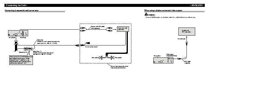
Connecting the UnitsConnecting to separately sold power amp When using a display connected video outputs WARNING Never install the display in a location where it is visible to the driver while driving. Connect with RCA cables (sold separately) Power amp (sold separately) Display with RCA input jacks This product Rear output To video input Blue/white Connect to system control terminal of the power amp (max. 300 mA 12 V DC). System remote control Blue/white (7*) Blue/white (6*) Connect to auto-antenna relay control terminal (max. 300 mA 12 V DC). Video output This product (VIDEO OUTPUT) The pin position of the ISO connector will Rear speaker + + Rear speaker 1.5 m differ depends on the type of vehicle. ? ? Connect 6* and 7* when Pin 5 is an antenna control type. In another type of RCA cable vehicle, never connect 6* and 7*. (supplied) Perform these connections when using the optional amplifier.
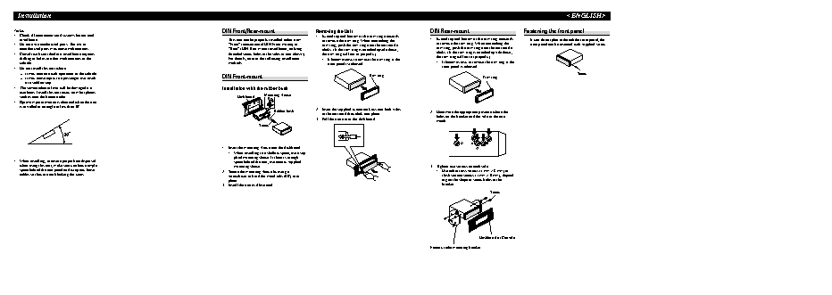
InstallationNote: DIN Front/Rear-mount Removing the Unit DIN Rear-mount Fastening the front panel • Check all connections and systems before final 1. Extend top and bottom of the trim ring outwards installation. This unit can be properly installed either from to remove the trim ring. When reattaching the 1. Extend top and bottom of the trim ring outwards If you do not plan to detach the front panel, the • Do not use unauthorized parts. The use of “Front” (conventional DIN Front-mount) or trim ring, push the trim ring onto the unit until it to remove the trim ring. When reattaching the front panel can be fastened with supplied screw. unauthorized parts may cause malfunctions. “Rear” (DIN Rear-mount installation, utilizing clicks. (If the trim ring is attached upside down, trim ring, push the trim ring onto the unit until it • Consult with your dealer if installation requires threaded screw holes at the sides of unit chassis). the trim ring will not fit properly.) clicks. (If the trim ring is attached upside down, drilling of holes or other modifications of the For details, refer to the following installation • It becomes easy to remove the trim ring if the the trim ring will not fit properly.) vehicle. methods. front panel is released. • It becomes easy to remove the trim ring if the • Do not install this unit where: front panel is released. — it may interfere with operation of the vehicle. Trim ring Screw — it may cause injury to a passenger as a result DIN Front-mount Trim ring of a sudden stop. • The semiconductor laser will be damaged if it Installation with the rubber bush overheats. Install this unit away from hot places Mounting sleeve such as near the heater outlet. Dashboard • Optimum performance is obtained when the unit 182 1 1 182 is installed at an angle of less than 30°. 2. Insert the supplied extraction keys into both sides 53 Rubber bush 2. Determine the appropriate position where the 53 of the unit until they click into place. holes on the bracket and the side of the unit 3. Pull the unit out of the dashboard. match. Screw 1. Insert the mounting sleeve into the dashboard. • When installing in a shallow space, use a sup- plied mounting sleeve. If there is enough • When installing, to ensure proper heat dispersal space behind the unit, use factory supplied when using this unit, make sure you leave ample mounting sleeve. 3. Tighten two screws on each side. space behind the rear panel and wrap any loose 2. Secure the mounting sleeve by using a • Use either truss screws (5 mm ? 8 mm) or cables so they are not blocking the vents. screwdriver to bend the metal tabs (90°) into flush surface screws (5 mm ? 9 mm), depend- place. ing on the shape of screw holes in the 3. Install the unit as illustrated. bracket. Screw Dashboard or Console Factory radio mounting bracket