На сайте 123396 инструкций общим размером 499.32 Гб , которые состоят из 6234837 страниц
Фото


Руководство пользователя PIONEER DEH-X5800BT. Основные функции, характеристики и условия эксплуатации изложены на 32 страницах документа в pdf формате.
Доступно к просмотру 31 страница. Рекомендуем вам скачать файл инструкции, поскольку онлайн просмотр документа может сильно отличаться от оригинала.
CD RDS RECEIVER
AUTORADIO CD RDS
SINTOLETTORE CD RDS                                                                                           English
REPRODUCTOR DE CD CON RECEPTOR RDS
CD RDS-EMPFANGER
CD RDS-ONTVANGER
CD RDS ПРИЕМНИК                                                                                               Francais
DEH-X5800BT                                                                                                   Italiano
DEH-4800BT                                                                                                    Espanol
Installation Manual
Manuel d’installation       Deutsch
Manuale d’installazione
Manual de instalacion
Installationsanleitung       Nederlands
Installatiehandleiding
Руководство по установке           Русский
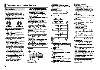
Microphone (4 m)           Black (chassis ground)
Connections/Installation                               Rear output or subwoofer output  Blue/white
Front output (Only for DEH-X5800BT)  The pin position of the ISO connector
–Never cut the insulation of the power   Antenna input   will differ depending on the type of
Connections                                              Fuse (10 A)                vehicle. Connect    and    when Pin 5
cable of this unit in order to share the
power with other devices. The current   Wired remote input  is an antenna control type. In another
Important                capacity of the cable is limited.  Hard-wired remote control adapter can   type of vehicle, never connect    and
• When installing this unit in a vehicle   –Use a fuse of the rating prescribed.  be connected (sold separately).  .
without an ACC (accessory) position on   –Never wire the negative speaker cable    Blue/white
the ignition switch, failure to connect the   directly to ground.  Power cord      Connect to the system control terminal
red cable to the terminal that detects   –Never band together negative cables of   of the power amp (max. 300 mA 12 V
operation of the ignition key may result   multiple speakers.                      DC).
in battery drain.         • When this unit is on, control signals are              Blue/white
sent through the blue/white cable.                       Connect to the auto-antenna relay
Connect this cable to the system remote                  control terminal (max. 300 mA 12 V DC).
control of an external power amp or the                  Speaker leads
vehicle’s auto-antenna relay control                     White: Front left
ACC position   No ACC position  terminal (max. 300mA 12 V DC). If the              White/black: Front left
• Use of this unit in conditions other than   vehicle is equipped with a glass antenna,   Gray: Front right
Gray/black: Front right
the following could result in fire or   connect it to the antenna booster power    Green: Rear left    or subwoofer
malfunction.              supply terminal.                                         Green/black: Rear left    or subwoofer
–Vehicles with a 12-volt battery and   • Never connect the blue/white cable to
negative grounding.       the power terminal of an external power                  Violet: Rear right    or subwoofer
–Speakers with 50 W (output value) and   amp. Also, never connect it to the power   Violet/black: Rear right    or subwoofer
4 ? to 8 ? (impedance value).  terminal of the auto antenna. Doing so
• To prevent a short-circuit, overheating or   may result in battery drain or a     Orange/white (Only for DEH-X5800BT)
malfunction, be sure to follow the   malfunction.                                  Connect to a car’s illumination signal.
directions below.         • The black cable is ground. Ground cables               ISO connector
–Disconnect the negative terminal of the   for this unit and other equipment       In some vehicles, the ISO connector
battery before installation.  (especially, high-current products such as   To power cord input  may be divided into two. In this case, be
–Secure the wiring with cable clamps or   power amps) must be wired separately. If   Depending on the kind of vehicle, the   sure to connect to both connectors.
adhesive tape. Wrap adhesive tape   they are not, an accidental detachment   function of    and    may be different.
around wiring that comes into contact   may result in a fire or malfunction.  In this case, be sure to connect    to      NOTES
with metal parts to protect the wiring.                 and  to  .               • Change the initial menu of this unit. Refer
–Place all cables away from moving parts,   This unit   Yellow                    to [SP-P/O MODE]. The subwoofer output
such as the shift lever and seat rails.                 Back-up (or accessory)    of this unit is monaural.
–Place all cables away from hot places,                 Yellow                   • When using a subwoofer of 70 W (2 ?), be
such as near the heater outlet.                         Connect to the constant 12 V supply   sure to connect the subwoofer to the
–Do not connect the yellow cable to the                 terminal.                 violet and violet/black leads of this unit.
battery by passing it through the hole                  Red                       Do not connect anything to the green
to the engine compartment.                              Accessory (or back-up)    and green/black leads.
–Cover any disconnected cable                           Red
connectors with insulating tape.                        Connect to terminal controlled by the   Power amp (sold separately)
–Do not shorten any cables.  Power cord input           ignition switch (12 V DC).  Perform these connections when using the
Microphone input             Connect leads of the same color to each   optional amplifier.
other.
2 En
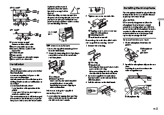
• Optimum performance is
DEH-X5800BT                                                                        Installing the microphone
obtained when the unit is
installed at an angle of less
than 60°.                                             The microphone should be placed directly
• When installing, to ensure proper heat   2 Tighten two screws on each side.  in front of the driver at a suitable distance
dispersal when using this unit, make sure             to pick up their voice clearly.
you leave ample space behind the rear                     CAUTION
panel and wrap any loose cables so they               It is extremely dangerous to allow the
are not blocking the vents.                                                      English
microphone lead to become wound
around the steering column or shift lever.
Be sure to install the microphone in such a
DEH-4800BT                                                 Tapping screw (5 mm ? 9 mm, not
Leave ample   5 cm             supplied with product)  way that it will not obstruct driving. It is
space                                                 recommended to use the clamps (sold
Mounting bracket       separately) to arrange the lead.
Dashboard or console
5 cm              Removing the unit (installed with   To install on the sun visor
System remote control                                 the supplied mounting sleeve)  1 Fit the microphone lead into the
Connect to blue/white cable.                                                       groove.
Power amp (sold separately)  DIN mount installation   1 Remove the trim ring.
Connect with RCA cables (sold   1 Insert the supplied mounting sleeve                          Microphone
separately)                into the dashboard.                                                 lead
To front output           2 Secure the mounting sleeve by using a                              Groove
Front speaker              screwdriver to bend the metal tabs
To rear output or subwoofer output  (90°) into place.
Rear speaker or subwoofer
Trim ring
Installation                                               Notched tab            2 Install the microphone clip on the sun
• Releasing the front panel allows easier   visor.
Important                                              access to the trim ring.  Lowering the sun visor reduces the
• Check all connections and systems before               • When reattaching the trim ring, point   voice recognition rate.
final installation.                                      the side with the notched tab down.
• Do not use unauthorized parts as this                2 Insert the supplied extraction keys
may cause malfunctions.      Dashboard                  into both sides of the unit until they
• Consult your dealer if installation requires   Mounting sleeve  click into place.
drilling of holes or other modifications to   • Make sure that the unit is installed   3 Pull the unit out of the dashboard.
the vehicle.                securely in place. An unstable
• Do not install this unit where:  installation may cause skipping or
–it may interfere with operation of the   other malfunctions.
vehicle.                  When not using the supplied
–it may cause injury to a passenger as a   mounting sleeve
result of a sudden stop.
• The semiconductor laser will be damaged   1 Determine the appropriate position     Microphone clip
if it overheats. Install this unit away from   where the holes on the bracket and
hot places such as near the heater outlet.  the side of the unit match.
En  3