На сайте 123401 инструкция общим размером 499.33 Гб , которые состоят из 6234961 страницы
Фото

Руководство пользователя PIONEER SVM-1000. Основные функции, характеристики и условия эксплуатации изложены на 326 страницах документа в pdf формате.
Доступно к просмотру 326 страниц. Рекомендуем вам скачать файл инструкции, поскольку онлайн просмотр документа может сильно отличаться от оригинала.
01_SVM-1000_En.book  1 ???  2007?10?16? ??? ??9?22?
SOUND & VISION MIXER
TABLE DE MIXAGE SON ET VIDEO
SOUND & VISION-MISCHPULT
MIXER AUDIO E VIDEO
MENGPANEEL VOOR GELUID & BEELD
CONSOLA DE MEZCLA DE SONIDO Y VISION
АУДИО И ВИДЕО МИКШЕР
SVM-1000
Operating Instructions
Mode d’emploi
Bedienungsanleitung
Istruzioni per l’uso
Handleiding
Manual de instrucciones
01_SVM-1000_En.book  2 ???  2007?10?16? ??? ??9?22?
Thank you for buying this Pioneer product.
Please read through these operating instructions so you will know how to operate your model properly. After you have finished
reading the instructions, put them away in a safe place for future reference.
In some countries or regions, the shape of the power plug and power outlet may sometimes differ from that shown in the
explanatory drawings. However the method of connecting and operating the unit is the same.
If the AC plug of this unit does not match the AC
IMPORTANT                                                              outlet you want to use, the plug must be removed
CAUTION                                   and appropriate one fitted. Replacement and
mounting of an AC plug on the power supply cord of
RISK OF ELECTRIC SHOCK                       this unit should be performed only by qualified
DO NOT OPEN
service personnel. If connected to an AC outlet, the
The lightning flash with arrowhead symbol,   CAUTION:  The exclamation point within an equilateral   cut-off plug can cause severe electrical shock. Make
within an equilateral triangle, is intended to   TO PREVENT THE RISK OF ELECTRIC   triangle is intended to alert the user to the   sure it is properly disposed of after removal.
alert the user to the presence of uninsulated   SHOCK, DO NOT REMOVE COVER (OR   presence of important operating and   The equipment should be disconnected by removing
"dangerous voltage" within the product's   BACK).  NO USER-SERVICEABLE PARTS   maintenance (servicing) instructions in the   the mains plug from the wall socket when left
enclosure that may be of sufficient   INSIDE.  REFER SERVICING TO QUALIFIED   literature accompanying the appliance.
magnitude to constitute a risk of electric   SERVICE PERSONNEL.         unused for a long period of time (for example, when
shock to persons.                                                       on vacation).           D3-4-2-2-1a_A_En
D3-4-2-1-1_En-A
Replacement and mounting of an AC plug on the power supply cord of this unit should be performed only by qualified   CAUTION
service personnel.                                                       The POWER switch on this unit will not completely
shut off all power from the AC outlet. Since the
IMPORTANT: THE MOULDED PLUG                                             power cord serves as the main disconnect device for
This appliance is supplied with a moulded three pin mains plug for your safety and convenience. A 10 amp fuse is fitted in this plug. Should the   the unit, you will need to unplug it from the AC outlet
fuse need to be replaced, please ensure that the replacement fuse has a rating of 10 amps and that it is approved by ASTA or BSI to BS1362.
to shut down all power. Therefore, make sure the
Check for the ASTA mark    or the BSI mark    on the body of the fuse.  unit has been installed so that the power cord can
be easily unplugged from the AC outlet in case of an
If the plug contains a removable fuse cover, you must ensure that it is refitted when the fuse is replaced. If you lose the fuse cover the plug
must not be used until a replacement cover is obtained. A replacement fuse cover can be obtained from your local dealer.  accident. To avoid fire hazard, the power cord should
also be unplugged from the AC outlet when left
If the fitted moulded plug is unsuitable for your socket outlet, then the fuse shall be removed and the plug cut off and disposed of   unused for a long period of time (for example, when
safely. There is a danger of severe electrical shock if the cut off plug is inserted into any 13 amp socket.
on vacation).           D3-4-2-2-2a_A_En
If a new plug is to be fitted, please observe the wiring code as shown below. If in any doubt, please consult a qualified electrician.
WARNING
IMPORTANT: The wires in this mains lead are coloured in accordance with the following code:
This equipment is not waterproof. To prevent a fire
Blue : Neutral    Brown : Live
As the colours of the wires in the mains lead of this appliance may not correspond with the coloured markings identifying the terminals in   or shock hazard, do not place any container filled
your plug, proceed as follows ;                                        with liquid near this equipment (such as a vase or
The wire which is coloured BLUE must be connected to the terminal which is marked with the    flower pot) or expose it to dripping, splashing, rain
letter N or coloured BLACK.                                        or moisture.
The wire which is coloured BROWN must be connected to the terminal which is marked with the    D3-4-2-1-3_B_En
letter L or coloured RED.
VENTILATION CAUTION
How to replace the fuse: Open the fuse compartment with a screwdriver and replace the fuse.  When installing this unit, make sure to leave space
D3-4-2-1-2-2_B_En  around the unit for ventilation to improve heat
radiation (at least 5 cm at rear, and 3 cm at each
Operating Environment               WARNING                             side).
Operating environment temperature and humidity:  Before plugging in for the first time, read the following   WARNING
+5 ?C – +35 ?C (+41 ?F – +95 ?F); less than 85 %RH    section carefully.  Slots and openings in the cabinet are provided for
(cooling vents not blocked)
The voltage of the available power supply differs   ventilation to ensure reliable operation of the
Do not install this unit in a poorly ventilated area, or in   according to country or region. Be sure that the   product, and to protect it from overheating. To
locations exposed to high humidity or direct sunlight (or   power supply voltage of the area where this unit   prevent fire hazard, the openings should never be
strong artificial light)   D3-4-2-1-7c_A_En  will be used meets the required voltage (e.g., 230 V   blocked or covered with items (such as newspapers,
WARNING                             or 120 V) written on the rear panel.   D3-4-2-1-4_A_En  table-cloths, curtains) or by operating the
To prevent a fire hazard, do not place any naked                        equipment on thick carpet or a bed.   D3-4-2-1-7b_A_En
flame sources (such as a lighted candle) on the
equipment.
D3-4-2-1-7a_A_En
This product complies with the Low Voltage Directive
2006/95/EC and EMC Directive  2004/108/EC.
If you want to dispose this product, do not mix it with general household waste. There is a separate collection system for used   D3-4-2-1-9a_A_En
electronic products in accordance with legislation that requires proper treatment, recovery and recycling.
Private households in the member states of the EU, in Switzerland and Norway may return their used electronic products free of charge to
designated collection facilities or to a retailer (if you purchase a similar new one).  POWER-CORD CAUTION
Handle the power cord by the plug. Do not pull out the
For countries not mentioned above, please contact your local authorities for the correct method of disposal.  plug by tugging the cord and never touch the power
By doing so you will ensure that your disposed product undergoes the necessary treatment, recovery and recycling and thus prevent potential   cord when your hands are wet as this could cause a
negative effects on the environment and human health.                  short circuit or electric shock. Do not place the unit, a
K058_A_En
piece of furniture, etc., on the power cord, or pinch the
cord. Never make a knot in the cord or tie it with other
cords. The power cords should be routed such that they
are not likely to be stepped on. A damaged power cord
can cause a fire or give you an electrical shock. Check
the power cord once in a while. When you find it
damaged, ask your nearest PIONEER authorized
service center or your dealer for a replacement.   S002_En
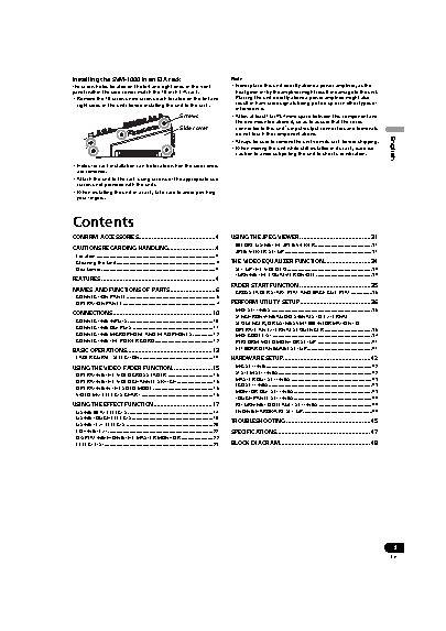
01_SVM-1000_En.book  3 ???  2007?10?16? ??? ??9?22?
Installing the SVM-1000 in an EIA rack             Note
The screw holes located on the left and right ends of the front   • Never place this unit directly above a power amplifier, as the
panel (within the side cover) match the 19-inch EIA rack.  heat given off by the amplifier might result in damage to the unit.
• Remove the 10 screws (five screws each located on the left and   Placing the unit directly above a power amplifier might also
right sides of the unit) before installing the unit to the rack.  result in ham radio signals being picked up or in other types of
interference.
Screws          • Allow at least 1U (43.7 mm) space between this component and
the one mounted above it, so as to assure that the cords
Side cover        connected to this unit's input/output connectors and terminals
do not touch the component above.
• Always be sure to remove the unit from its rack before shipping.
• When moving the unit while still installed in its rack, exercise   English
caution to avoid subjecting the unit to shocks or vibration.
• Holes for rack installation can be located when the side covers
are removed.
• Attach the unit to the rack using screws of the appropriate size
(screws not provided with the unit).
• When installing the unit in a rack, take care to avoid pinching
your fingers.
Contents
CONFIRM ACCESSORIES..............................................4  USING THE JPEG VIEWER..........................................31
BEFORE USING THE JPEG VIEWER...........................................31
CAUTIONS REGARDING HANDLING............................4
JPEG VIEWER SETUP..................................................................31
Location.......................................................................................... 4
Cleaning the Unit........................................................................... 4  THE VIDEO EQUALIZER FUNCTION............................34
Disclaimer ...................................................................................... 4  SET UP THE VIDEO EQ................................................................34
TURNING THE EQUALIZER ON/OFF ..........................................34
FEATURES ....................................................................4
FADER START FUNCTION ..........................................35
NAMES AND FUNCTIONS OF PARTS ...........................6
CROSS FADER START PLAY AND BACK CUE PLAY................35
CONNECTION PANEL ................................................................... 6
OPERATION PANEL ...................................................................... 7  PERFORM UTILITY SETUP ..........................................36
MIDI SETTINGS ............................................................................36
CONNECTIONS...........................................................10
SYNCHRONIZING AUDIO SIGNALS TO EXTERNAL
CONNECTING INPUTS................................................................ 10  SEQUENCER, OR USING SVM-1000 INFORMATION TO
CONNECTING OUTPUTS ............................................................ 11  OPERATE AN EXTERNAL SEQUENCER ....................................36
CONNECTING MICROPHONE AND HEADPHONES ............... 12  MIDI CODE LIST...........................................................................37
CONNECTING THE POWER CORD............................................ 12  PERFORM VIDEO MONITOR SETUP .........................................41
BASIC OPERATIONS...................................................13  KEYBOARD LANGUAGE SETUP.................................................41
FADER CURVE  SELECTION....................................................... 14  HARDWARE SETUP....................................................42
USING THE VIDEO FADER FUNCTION........................15  MIC SETTING ................................................................................42
SYSTEM SETTINGS.......................................................................42
OPERATING THE VIDEO CROSS FADER .................................. 15
OPERATING THE VIDEO CHANNEL SWITCH ........................... 15  MASTER OUT SETTINGS .............................................................43
OPERATING IN THE SOLO MODE ............................................. 16  LCD SETTINGS..............................................................................43
VIDEO MIX EFFECTS CHART...................................................... 16  MONITOR OUT SETTINGS...........................................................43
TOUCH PANEL SETTINGS...........................................................44
USING THE EFFECT FUNCTION...................................17  RETURNING TO DEFAULT SETTINGS ........................................44
USING BEAT EFFECTS ................................................................ 17  ENDING HARDWARE SET UP....................................................44
USING TOUCH EFFECTS............................................................. 19  TROUBLESHOOTING ..................................................45
USING TEXT EFFECTS ................................................................. 20
EDITING TEXT............................................................................... 22  SPECIFICATIONS........................................................47
DISPLAYING/HIDING THE MASTER MONITOR........................ 22
EFFECT LIST.................................................................................. 23  BLOCK DIAGRAM......................................................48
3
En