На сайте 123424 инструкции общим размером 499.44 Гб , которые состоят из 6235949 страниц
Фото

Руководство пользователя BEHRINGER CABLE TESTER CT100. Основные функции, характеристики и условия эксплуатации изложены на 7 страницах документа в pdf формате.
Доступно к просмотру 7 страниц. Рекомендуем вам скачать файл инструкции, поскольку онлайн просмотр документа может сильно отличаться от оригинала.
User Manual
CABLE TESTER CT100
Professional 6-in-1 Cable Tester
2  CABLE TESTER CT100 User Manual
1.  Introduction
Congratulations! With the CT100, you have purchased an indispensable tool that
enables you to easily check the most common cables used by musicians and sound
engineers. Faulty cables are a common cause of failure in live and studio situations.
This microprocessor-controlled device was designed to ensure fast, reliable problem
location. Various test modes and the included belt clip add to its flexibility.
2.  Cable Tester Mode
?  Move the ON switch to the CABLE TESTER position.
Insert one end of your cable into any OUT jack of the CT100. Connect the other end of the
cable to any IN jack. The LEDs will indicate which input pins are connected to each output
pin. Additionally, the GROUNDED SHIELD LED indicates whether a XLR OUT jack’s shield is
connected to the pin 1/sleeve signal.
2.1  How to test intermittent connections
The following method allows you to detect intermittent connections caused by wire
breaks or faulty solder points. While in CABLE TESTER MODE, press RESET to store the
current cable-wiring display and to clear the INTERMITTENT LEDs. Move the cable
vigorously in all directions and watch the LEDs. Any change in wiring or break in the
signal flow will cause the LED of the corresponding input pin to light up. The LED will
stay lit until RESET is pressed again, assuring detection of even the shortest breaks in the
signal flow. It is a good idea to repeat the test after resetting the LEDs to double-check
the initial results.
3.  Installed Cable Tester Mode
This mode enables you to test cables in fixed installations or situations that don’t allow
you to connect both ends of the cable to the CT100.
?  Hold down the RESET button while moving the ON switch to the CABLE TESTER
position. The ON LED will blink to indicate that the CT100 is in INSTALLED CABLE
TESTER MODE.
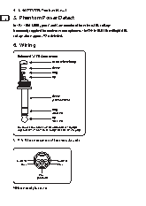
3  CABLE TESTER CT100 User Manual
To test a cable for short circuits, connect one end of the cable to the appropriate
OUT jack of the CT100. The display works as in CABLE TESTER MODE (see chapter 2).
However, it now indicates connections between out pins. If no LEDs light, the cable is free
of short circuits.
3.1  Continuity check in Installed Cable Tester Mode
For a continuity check, connect a shorting jack (a jack in which pins are short-circuited
to one another) to the other end of the cable. If there are no breaks in the signal flow,
the display will show the corresponding pins as being shorted to each other. If the display
indicates no short circuit, there is a break in the signal flow.
?  The testing of intermittent connections works exactly as in CABLE TESTER MODE
(see chapter 2.1).
?  INSTALLED CABLE TESTER MODE will not indicate connections between out and
in pins. This is done in CABLE TESTER MODE (see chapter 2).
4.  Test Tone Mode
?  Move the ON switch to the position TEST TONE.
?  Do not use the TEST TONE MODE for MIDI cables!
TEST TONE MODE may be used to check signal flow and to facilitate level adjustments.
It routes a test tone to the “+ pin” (pin 2/tip) of all OUT jacks. Use the TEST TONE LEVEL
switch to choose between +4 dBu, -10 dBV, or -50 dBV mic level. Please note that this
mode is not intended to work as a voltage standard and that battery voltage will affect
the test tone output level.
4.1  Selection between 1 kHz and 440 Hz
While in TEST TONE MODE, pressing RESET toggles between 1 kHz and 440 Hz. The TEST
TONE LED indicates the selected frequency: On = 1 kHz, Off = 440 Hz.