На сайте 123429 инструкций общим размером 499.45 Гб , которые состоят из 6236153 страниц
Фото

Руководство пользователя GORENJE GBK 100 LN RN. Основные функции, характеристики и условия эксплуатации изложены на 32 страницах документа в pdf формате.
Доступно к просмотру 27 страниц. Рекомендуем вам скачать файл инструкции, поскольку онлайн просмотр документа может сильно отличаться от оригинала.
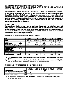
Dear customer, we thank you for purchasing our product.
PLEASE READ THE INSTRUCTIONS THOROUGHLY PRIOR TO THE INSTALLATION AND
FIRST OPERATION OF THE WATER HEATER.
This water heater has been manufactured in compliance with the relevant standards and tested
by the relevant authorities as indicated by the Safety Certificate and the  Electromagnetic
Compatibility  Certificate.  Its  basic  technical  properties are stated upon the nameplate, glued
between the connection pipes. The water heater may be connected to water and electric power
supply only by a qualified  specialist.  The  reach  in its inside due to the repair or removal of
limestone and checking and replacement of anti-corrosion protection anode may be performed
only by an authorised service workshop.
INSTALLATION
The water heater shall be built as close as possible to the outlets.It has to be fitted to the wall
using appropriate rag bolts with minimum diameter of 8 mm. In case the wall in question cannot
support the weight three times that of the water heater filled with water, the relevant section of
the wall where the heater is to be installed, must be suitably reinforced. GBK water heater must
be mounted to the wall in the upright position.
TECHNICAL CHARACTERISTICS OF WATER HEATER
Type                      GB 80    GB 100    GB 120   GB 150   GB 200
GBK 80    GBK 100    GBK 120    GBK 150    GBK 200
Model
LN/RN (V)   LN/RN (V)   LN/RN (V)   LN/RN (V)   LN/RN (V)
Volume                                           [l]   80   100   120   150   200
Rated Pressure                           [MPa]   0.6
Weight / Filled with water              [kg]   51/131   56/156   62/182   72/222   90/290
Anti-corrosion protection of tank        Emailed & Mg Anode
Power of electrical heater              [W]   2000
Connection voltage                       [V~]   230
Protection class                              I
Degree of protection                         IP 25
1)
40
Heating time to 75 °C                   [h]   3 05  3 55  4 35  5 45  7
Quantity of mixed water at 40°C    [l]   151   189   226   276   360
2)
Energy consumption         [kWh/24h]   1.39   1.58   1.77   2.05   2.50
1)  Time required for the electric heating element to heat the entire tank volume, at the water supply temperature
of 15°C.
2)  Power consumption required for the temperature of water in the water heater to be maintained at 65°C, at the
room temperature of 20°C, measured in accordance with the DIN 44532 standard.
TECHNICAL CHARACTERISTICS OF HEAT EXCHANGER
GBK 80    GBK 100    GBK 120    GBK 150    GBK 200
LN/RN (V)   LN/RN (V)   LN/RN (V)   LN/RN (V)   LN/RN (V)
Nominal pressure                                       [MPa]   0.6
Max. inlet temperature of heating medium   [°C]   85
Surface of transmitter                                   [m ] 2  0.72  0.88
3)
Heat flow of heat transmitter                      [W]   14400   17600
3)  Heating medium: inlet temperature 70°C, flow 3000 l/h.     Sanitary water: inlet temperature 10°C, outlet
temperature 45°C, flow 437 l/h.
3
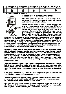
GBK 80 LN/RN (V)   GBK 100 LN/RN (V)   GBK 120 LN/RN (V)   GBK 150 LN/RN (V)   GBK 200 LN/RN (V)
A       803           948           1103          1318         1510
B       207           202           207           222           430
C       565           715           865           1065         1050
D       340           416           416           416           416
Connection and installation dimensions [mm].
CONNECTION TO THE WATER SUPPLY SYSTEM
Inlet  and  outlet  of  water  are on the water heater pipes marked
with colour. The supply of cold water is marked  with  blue,  the
outlet of warm water is marked with red.
The water heater can be connected to  the  water  supply  in  two
manners. Closed pressure  system of connection enables the
outlet of water on several outlet  spots, non-pressure system
enables  only  one outlet point. With regard to the system of
connection chosen, also the suitable mixing  taps  must  be
purchased. By open non-pressure system it must before the water
heater a safety valve be built-in preventing the running of water of
the tank if in the network the water runs short. By this system of
connection, the cross-flow mixing tap must be used. In the water heater, due to the heating the
volume of water is increasing, which causes the dropping of water of the mixing tap pipe. By
strong squeezing of knob of the mixing tap the dropping of water can not be prevented, but the
mixing tap can only be damaged. By closed pressure system of connection on the outlet spots
the pressure mixing tap must be used. For safety reasons the supply pipe must be fitted with a
return safety valve or  alternatively, a valve of the safety class that prevents the pressure in the
tank from exceeding the nominal pressure by more than 0.1 MPa.
By heating of water in the water heater the pressure of water in the tank is increasing to the limit
which is adjusted in the safety valve. Because the return of water back to the water supply is
prevented, dropping of water from outlet opening of the safety valve can occur. The dropping
water may be let to the outlet over an intercepting accessory which is placed under the safety
valve. In order to do this you should first unscrew the protective cover off the water heater. In
case the existing plumbing does not enable you to pipe the dripping water from the return safety
valve into the drain, you can avoid the dripping by installing a 3-litre expansion tank on the inlet
water pipe of the boiler.
You should ensure that the return safety valve is functioning properly by checking it on a regular
basis i.e. every 14 days. To check the valve, you should open the outlet of the return safety
valve by turning the handle or unscrewing the nut of the valve (depending on the type of the
valve). The valve is operating properly if the water comes out of the nozzle when the outlet is
open.
Between the water heater and safety valve no closing valve may be built-in because it
would disable the operation of non-return safety valve.
The water heater may be connected to the water supply in the house without reduction valve if
the pressure in the network is lower than 0.5 MPa. If the pressure in the network surpasses 1.0
MPa, two reduction valves must be built-in, one after another.
Prior to the electric connection, the water heater must mandatorily be filled with water. By first
filling the tap for the hot water upon the mixing tap must be opened. When the heater is filled
with water, the water starts to run through the outlet pipe of the mixing tap.
4
Closed-circuit (pressure) system                       Open-circuit (gravity) system
Key:
1 - Safety valve
2 - Test valve
3 - Non-return valve
4 - Pressure-reducing valve
5 - Stop valve
6 - Testing piece
7 - Funnel outlet to the drain
H - Cold water
T - Hot water
Combined GBK water heater operates in the same manner as the electrical GB water heater
however, it has also been fitted with the  cooling water heat exchanger allowing the sanitary
water to be heated by alternative sources of energy (e.g. central heating, solar collector or heat
pump). The two heating systems - electrical heating element and heat exchanger - can operate
singly or concurrently. While the combined water heater is connected to the water supply system
in the same manner as the GB model, the connection to the additional energy source has to be
made as well. The inlet of the heating medium into the cooling water heat exchanger is colour-
coded blue, while the outlet is colour-coded red. GBK water heaters can also be connected to
the return hot water pipe. The return hot water pipe makes hot water instantly available at all
points of use simultaneously. The return pipe can be connected to the inlet point at the top of the
water heater after removing the  plastic  cap and unscrewing the stopper. The return pipe
elements can also be purchased at any authorised dealer of our products at a later stage.
POWER CONNECTION
The power lead must be fitted to the water heater prior to connecting the heater to the power
supply. In order to do this the plastic protective cover must be taken off by removing the plate
inserted into the front side of the cover. The plate can be released by carefully inserting a flat
screwdriver into the fissure between the plate and the protective cap, first next to the thermostat
knob and then into the fissure opposite the knob. Once loose, the plate can subsequently be
removed by hand. In order to remove the plastic protective cover, the thermostat knob must also
be removed and both fixing screws undone. The protective cover can be re-fitted following the
same procedure in reverse. The water heater must be connected to the power supply in
accordance with the requirements set out in  the relevant standards applying to the electrical
installations. For safety reasons, a switch should be installed on the lead connecting the heater
to the power grid, i.e. a switch disconnecting both power supply poles with the minimum of 3 mm
distance between the open contacts.
5