На сайте 123411 инструкций общим размером 499.36 Гб , которые состоят из 6235346 страниц
Фото
Руководство пользователя HOTPOINT-ARISTON 7OFH G IX RU/HA (FHG IX/HA). Основные функции, характеристики и условия эксплуатации изложены на 28 страницах документа в pdf формате.
Доступно к просмотру 26 страниц. Рекомендуем вам скачать файл инструкции, поскольку онлайн просмотр документа может сильно отличаться от оригинала.
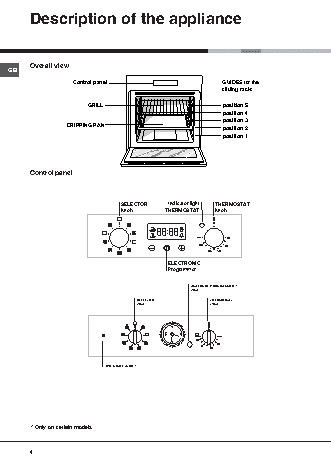
Operating Instructions
OVEN
Contents
GB
Installation, 2-3
GB            RS                                 Positioning
Electrical connections
English,1     ???????, 13
Description of the appliance, 4
Overall view
Control panel
Start-up and use, 5
Starting the oven
Using the cooking timer
Data plate
The electronic cooking programmer, 6
7OFH 837 C RU /HA                                 Analogue Programmer, 7
7OFTR 850 RU /HA
7OF 937 C.1 RU/HA                                 Cooking modes, 8-10
7OF 937 C.1 IX RU/HA                              Cooking modes
7OFH 837 C IX RU/HA                               Practical cooking advice
7OFQ 837 C.1 /HA
Cooking advice table
Precautions and tips, 11
General safety
Disposal
Respecting and conserving the environment
Assistance
Maintenance and care, 12
Switching the appliance off
Cleaning the appliance
Cleaning the oven door
Replacing the light bulb
Sliding Rack Kit assembly
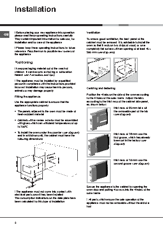
Installation
! Before placing your new appliance into operation   Ventilation
GB      please read these operating instructions carefully.
They contain important information for safe use, for  To ensure good ventilation, the back panel of the
installation and for care of the appliance.          cabinet must be removed. It is advisable to install the
oven so that it rests on two strips of wood, or on a
! Please keep these operating instructions for future  completely flat surface with an opening of at least 45 x
reference. Pass them on to possible new owners of    560 mm (see diagrams).
the appliance.
Positioning
560 mm.  45 mm.
! Keep packaging material out of the reach of
children. It can become a choking or suffocation
hazard. see Precautions and tips).
! The appliance must be installed by a qualified
person in compliance with the instructions provided.
Incorrect installation may cause harm to persons,    Centring and fastening
animals or may damage property.
Position the 4 tabs on the side of the oven according
Fitting the appliance
to the 4 holes of the outer frame. Adjust the tabs
Use the appropriate cabinet to ensure that the       according to the thickness of the cabinet side panel,
appliance functions properly.                        as shown below:
thickness of 20 mm: take off
•  The panels adjacent to the oven must be made of                      the removable part of the tab
heat-resistant material.                                              (see diagram)
•  Cabinets with a veneer exterior must be assembled
with glues which can withstand temperatures of up
to 100°C.
•  To install the oven under the counter (see diagram)                  thickness of 18 mm: use the
and in a kitchen unit, the cabinet must have the                      first groove, which has already
following dimensions:
been set in the factory (see
diagram)
547 mm. min.
23 mm.   45 mm.   593 mm.                                 thickness of 16 mm: use the
595 mm.         567 mm.  558 mm.                                       second groove (see diagram)
5 mm.
545 mm.
595 mm.
24 mm.                                       Secure the appliance to the cabinet by opening the
! The appliance must not come into contact with      oven door and putting 4 screws into the 4 holes of the
outer frame.
electrical parts once it has been installed.
The consumption indications on the data plate have   ! All parts which ensure the safe operation of the
been calculated for this type of installation.
appliance must not be removable without the aid of a
tool.
2
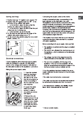
Centring and fixing*                                Connecting the supply cable to the mains
GB
“A”
“A”
“A”
1. Position brackets  “A”“A” against oven support       “BB BB B”.  Install a standardised plug corresponding to the
“C”
“C”
“C”
“A”
“A”
“A”
2. Position tabs  “C”“C” against brackets “A” “A”.  If the  load indicated on the data plate (see side).
thickness of the cabinet side panel:              The appliance must be directly connected to the mains
•  is 16 mm thick: place the tab so that the      using an omnipolar circuit-breaker with a minimum
number 16 written on it is facing you;            contact opening of 3 mm installed between the appliance
•  is 18 mm thick: place the tab so that the part  and the mains, suitable for the load indicated and
without any text is facing you;                   complying with current electrical regulations (the earthing
•  is 20 mm thick: do not fit the tab.            wire must not be interrupted by the circuit-breaker). The
3. Fix the brackets and tabs onto the edge of the   supply cable must not come into contact with surfaces
“D”.
“D”.
“D”.
cabinet side panel using screws  “D”.“D”.         with temperatures higher than 50°C.
4. Fix the oven to the cabinet using the screws and  ! The installer must ensure that the correct electrical
“E”.
“E”
plastic washers “E” “E”
“E”
connection has been made and that it is compliant
with safety regulations.
16       D C
16
Before connecting to the power supply, make sure that:
D C       A                       E                • The appliance is earthed and the plug is compliant
with the law.
16
16         C                     E              • The socket can withstand the maximum power of
D
the appliance, which is indicated on the data plate
(see below).
B
• The voltage must be in the range between the
Electrical connections                                values indicated on the data plate (see below).
! Ovens equipped with a three-pole power supply     • The socket is compatible with the plug of the
cable are designed to operate with alternating        appliance. If the socket is incompatible with the
current at the voltage and frequency indicated on     plug, ask an authorised technician to replace it. Do
the data plate located on the appliance (see below).  not use extension cords or multiple sockets.
Fitting the power supply cable
! Once the appliance has been installed, the power
1. Open the terminal       supply cable and the electrical socket must be easily
board by inserting a       accessible.
screwdriver into the
side tabs of the cover.    ! The cable must not be bent or compressed.
Use the screwdriver as
a lever by pushing it      ! The cable must be checked regularly and replaced
down to open the cover     by authorised technicians only (see Assistance).
(see diagram).
! The manufacturer declines any liability should
! The manufacturer declines any liability should
! The manufacturer declines any liability should
! The manufacturer declines any liability should
! The manufacturer declines any liability should
2. Loosen the cable        these safety measures not be observed.
these safety measures not be observed.
these safety measures not be observed.
these safety measures not be observed.
these safety measures not be observed.
clamp screw and
remove it, using a
screwdriver as a lever
(see figure).
3. Remove the wire
contact screws L-N-
, then fasten the wires
under the screw heads,
respecting the colour
code: Blue (N), Brown
(L) and Yellow-Green
Verde (  ).                * Only on certain models.
3