На сайте 123408 инструкций общим размером 499.34 Гб , которые состоят из 6235299 страниц
Фото
Руководство пользователя HOTPOINT-ARISTON 7HPC 640T (AN) R/HA. Основные функции, характеристики и условия эксплуатации изложены на 44 страницах документа в pdf формате.
Доступно к просмотру 42 страницы. Рекомендуем вам скачать файл инструкции, поскольку онлайн просмотр документа может сильно отличаться от оригинала.
Operating Instructions
HOB
Contents
GB
Installation, 2-5
GB            RS           ??                       Positioning
Electrical connection
English, 1   ????????? ??  ???????????? ??          Gas connection
Data plate
Burner and nozzle specifications
KZ
Description of the appliance, 6
?????                                        Overall view
Start-up and use, 7
Practical advice on using the burners
Precautions and tips, 8
General safety
Disposal
7HPC 640 /HA                                        Maintenance and care, 9
7HPC 640 X/HA                                       Switching the appliance off
7HPC 640 GH/HA                                      Cleaning the appliance
7HPC 631 /HA                                        Gas tap maintenance
7HPC 631 X/HA                                       Troubleshooting, 10
7HPC 640N /HA
7HPC 640N GH/HA
7HPC 640N X /HA
PC 640N /HA
PC 640N X/HA
7HPC 640 T GH /HA
7HPC 640 T R /HA
7HPC 640 T X /HA
GPN 64 NW RFH
GPN 64 NCI RFH
GPN 64 NI RFH
GPN 64 A CI RFH
GPN 64 O CI RFH
GPN 64 TA CI RFH
GPN 64 TO CI RFH
1
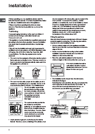
Installation
! Before operating your new appliance please read this  also be equipped with vents to allow gas to escape in the
GB      instruction booklet carefully. It contains important information  event of a leak. As a result LPG cylinders, whether
for safe use, installation and care of the appliance.  partially or completely full, must not be installed or stored
! Please keep these operating instructions for future  in rooms or storage areas that are below ground level
reference. Pass them on to possible new owners of the  (cellars, etc.). It is advisable to keep only the cylinder
appliance.                                             being used in the room, positioned so that it is not
subject to heat produced by external sources (ovens,
Positioning                                            fireplaces, stoves, etc. ) which could raise the
! Keep packaging material out of the reach of children. It  temperature of the cylinder above 50°C.
can become a choking or suffocation hazard (see      Fitting the appliance
Precautions and tips).
! The appliance must be installed by a qualified professional  Gas and mixed hobs are manufactured with type X degree
protection against overheating. The following precautions
according to the instructions provided. Incorrect installation  must be taken when installing the hob:
may cause harm to people and animals or may damage
property.                                            • Kitchen cabinets adjacent to the appliance and taller
! This unit may be installed and used only in permanently  than the top of the hob must be at least 600 mm from the
ventilated rooms in accordance with British Standard Codes  edge of the hob.
Of Practice: B.S. 6172 / B.S. 5440, Par. 2 and B.S. 6891  • Hoods must be installed according to their relative
Current Editions. The following requirements must be   installation instruction manuals and at a minimum
observed:                                              distance of 650 mm from the hob.
• The room must be equipped with an air extraction system  • Place the wall cabinets adjacent to the hood at a
that expels any combustion fumes. This may consist of a  minimum height of 420 mm from the hob (see figure).
hood or an electric fan that automatically starts each time
the appliance is switched on.                                         If the hob is installed beneath a
wall cabinet, the latter must be
situated at a minimum of 700 mm
700mm min.   420mm min.  above the hob (see figure).
600mm min.
In a chimney stack or branched flue.   Directly to
• The installation cavity should have the dimensions
(exclusively for cooking appliances)  the Outside
indicated in the figure.
• The room must also allow proper air circulation, as air is  Fastening hooks are provided, allowing you to fasten the
needed for combustion to occur normally. The flow of air  hob to tops that are between 20 and 40 mm thick. To
must not be less than 2 m /h per kW of installed power.  ensure the hob is securely fastened to the top, we
3
The air circulation system may     recommend you use all the hooks provided.
take air directly from the outside
by means of a pipe with an inner                          555 mm
cross section of  at least 100 cm ;        55 mm
2
A           the opening must not be
vulnerable to any type of                                           475 mm
Examples of ventilation holes
blockages.
for comburant air.
The system can also provide the
Adjacent  Room to be
air needed for combustion        Hook fastening diagram
Room   Vented
indirectly, i.e. from adjacent rooms
fitted with air circulation tubes as
described above. However, these
rooms must not be communal
Enlarging the ventilation slot  rooms, bedrooms or rooms that
between window and floor.                          Hooking position        Hooking position
may present a fire hazard.
for top H=20 mm         for top H=30 mm
• Liquid petroleum gas sinks to the floor as it is heavier
than air. Therefore, rooms containing LPG cylinders must
2
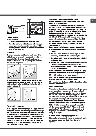
Front                       Connecting the supply cable to the mains
Install a standardised plug corresponding to the load  GB
indicated on the data plate.
The appliance must be directly connected to the mains
using an omnipolar circuit-breaker with a minimum contact
opening of 3 mm installed between the appliance and the
mains.  The circuit-breaker must be suitable for the charge
indicated and must comply with current electrical
regulations (the earthing wire must not be interrupted by the
Hooking position         Back                       circuit-breaker). The supply cable must not come into
for top H=40 mm                                     contact with surfaces with temperatures higher than 50°C.
! Use the hooks contained in the “accessory pack”   ! The installer must ensure that the correct electrical
• Where the hob is not installed over a built-in oven, a  connection has been made and that it is compliant with
wooden panel must be installed as insulation. This  safety regulations.
must be placed at a minimum distance of 20 mm from  Before connecting to the power supply, make sure that:
the lower part of the hob.                        • The appliance is earthed and the plug is compliant with
the law.
Ventilation                                         • The socket can withstand the maximum power of the
To ensure adequate ventilation, the back panel of the  appliance, which is indicated on the data plate.
cabinet must be removed. It is advisable to install the
oven so that it rests on two strips of wood, or on a  • The voltage is in the range between the values indicated
completely flat surface with an opening of at least 45 x  on the data plate.
560 mm (see diagrams).                              • The socket is compatible with the plug of the appliance. If
the socket is incompatible with the plug, ask an
authorised technician to replace it. Do not use extension
cords or multiple sockets.
560 mm.
45 mm.
! Once the appliance has been installed, the power supply
cable and the electrical socket must be easily accessible.
! The cable must not be bent or compressed.
! The cable must be checked regularly and replaced by
When installing the cooktop above a built-in oven   authorised technicians only (see Assistance).
without forced ventilation, ensure that there are air  ! The manufacturer declines any liability should these safety
inlets and outlets for ventilating the interior of the  measures not be observed.
cabinet adequately.                                 Gas connection
The appliance should be connected to the main gas supply
or to a gas cylinder in compliance with current national
regulations. Before carrying out the connection, make sure
the cooker is compatible with the gas supply you wish to
use. If this is not the case, follow the instructions indicated in
the paragraph “Adapting to different types of gas.”
When using liquid gas from a cylinder, install a pressure
regulator which complies with current national regulations.
! Check that the pressure of the gas supply is consistent
Electrical connection                               with the values indicated in Table 1 (“Burner and nozzle
Hobs equipped with a three-pole power supply cable are  specifications”). This will ensure the safe operation and
designed to operate with alternating current at the voltage  longevity of your appliance while maintaining efficient
and frequency indicated on the data plate (this is located  energy consumption.
on the lower part of the appliance). The earth wire in the
cable has a green and yellow cover. If the appliance is to  Connection with a rigid pipe (copper or steel)
be installed above a built-in electric oven, the electrical  ! Connection to the gas system must be carried out in such
connection of the hob and the oven must be carried out  a way as not to place any strain of any kind on the
separately, both for electrical safety purposes and to  appliance.
make extracting the oven easier.
3