На сайте 123387 инструкций общим размером 499.28 Гб , которые состоят из 6234324 страниц
Фото
Руководство пользователя HOTPOINT-ARISTON 7HKRO 642 TOX RU/HA. Основные функции, характеристики и условия эксплуатации изложены на 28 страницах документа в pdf формате.
Доступно к просмотру 27 страниц. Рекомендуем вам скачать файл инструкции, поскольку онлайн просмотр документа может сильно отличаться от оригинала.
Operating Instructions
HOB
Contents
GB
Installation, 2-4
GB           RS                                 Positioning
Electrical connection
English,1    ???????, 14
Description of the appliance, 5-6
Control panel
Extendable cooking zones
Start-up and use, 7-10
Switching on the hob
Switching on the cooking zones
Switching off the cooking zones
Power function
Heating elements
Programming the cooking duration
Timer
Control panel lock
7HKRO 642 D X RU/HA                              Switching off the hob
7HKRO 642 D Z RU/HA                              “Demo” mode
7HKRO 642 TO B RU/HA                             Practical advice on using the appliance
7HKRO 642 TO Z RU/HA                             Safety devices
7HKRO 642 TO X RU/HA                             Practical cooking advice
Precautions and tips, 11
General safety
Disposal
Care and maintenance, 12
Switching the appliance off
Cleaning the appliance
Disassembling the hob
Technical description of the models, 13
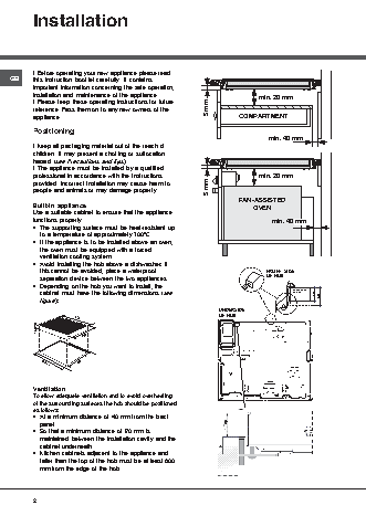
Installation
! Before operating your new appliance please read
GB      this instruction booklet carefully. It contains
important information concerning the safe operation,
installation and maintenance of the appliance.                           min. 20 mm
! Please keep these operating instructions for future
reference. Pass them on to any new owners of the         5 mm
appliance.                                                         COMPARTMENT
Positioning
min. 40 mm
! Keep all packaging material out of the reach of
children. It may present a choking or suffocation
hazard (see Precautions and tips).
! The appliance must be installed by a qualified
professional in accordance with the instructions                         min. 20 mm
provided. Incorrect installation may cause harm to
people and animals or may damage property.               5 mm
FAN-ASSISTED
Built-in appliance                                                      OVEN
Use a suitable cabinet to ensure that the appliance
functions properly.                                                          min. 40 mm
• The supporting surface must be heat-resistant up
to a temperature of approximately 100°C.
• If the appliance is to be installed above an oven,
the oven must be equipped with a forced
ventilation cooling system.
• Avoid installing the hob above a dishwasher: if
this cannot be avoided, place a waterproof                                FRONT SIDE
separation device between the two appliances.                             OF HOB
• Depending on the hob you want to install, the
cabinet must have the following dimensions (see                                   SUPPORTING  30  40
SURFACE
figure):
UNDERSIDE
OF HOB
590
48
520
490 +/- 1
560 +/- 1
Ventilation
To allow adequate ventilation and to avoid overheating
of the surrounding surfaces the hob should be positioned
as follows:
• At a minimum distance of 40 mm from the back
panel.
• So that a minimum distance of 20 mm is
maintained between the installation cavity and the
cabinet underneath.
• Kitchen cabinets adjacent to the appliance and
taller than the top of the hob must be at least 600
mm from the edge of the hob.
2
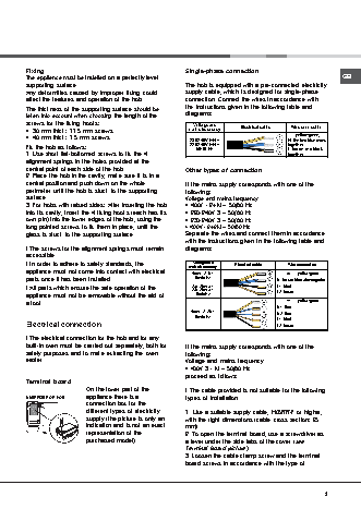
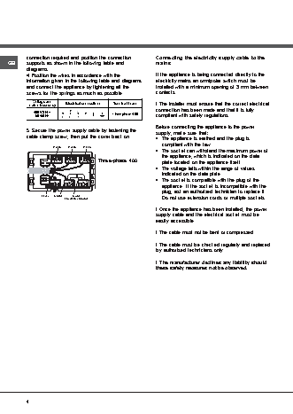
Fixing                                              Single-phase connection
The appliance must be installed on a perfectly level                                                    GB
supporting surface.                                 The hob is equipped with a pre-connected electricity
Any deformities caused by improper fixing could     supply cable, which is designed for single-phase
affect the features and operation of the hob.       connection. Connect the wires in accordance with
The thickness of the supporting surface should be   the instructions given in the following table and
taken into account when choosing the length of the  diagrams:
screws for the fixing hooks:                           Voltage and
• 30 mm thick: 17.5 mm screws                        mains frequency   Electrical cable   Wire connection
: yellow/green;
• 40 mm thick: 7.5 mm screws                          230-240V 1+N ~                  N: the two blue wires
Fix the hob as follows:                               220-240V 1+N ~                  together
50/60 Hz
L: brown and black
1. Use short flat-bottomed screws to fix the 4                                         together
alignment springs in the holes provided at the
central point of each side of the hob.              Other types of connection
2. Place the hob in the cavity, make sure it is in a
central position and push down on the whole         If the mains supply corresponds with one of the
perimeter until the hob is stuck to the supporting  following:
surface.                                            Voltage and mains frequency
3. For hobs with raised sides: After inserting the hob  • 400V - 2+N ~ 50/60 Hz
into its cavity, insert the 4 fixing hooks (each has its  • 220-240V 3 ~ 50/60 Hz
own pin) into the lower edges of the hob, using the  • 230-240V 3 ~ 50/60 Hz
long pointed screws to fix them in place, until the  • 400V - 2+2N ~ 50/60 Hz
glass is stuck to the supporting surface.           Separate the wires and connect them in accordance
with the instructions given in the following table and
! The screws for the alignment springs must remain  diagrams:
accessible.
! In order to adhere to safety standards, the        mains frequency   Electrical cable   Wire connection
Voltage and
appliance must not come into contact with electrical  400V - 2+N ~                       :  yellow/green;
parts once it has been installed.                      50/60 Hz                    N: the two blue wires together
! All parts which ensure the safe operation of the    230-240V 3 ~                 L1: black
220-240V 3 ~
appliance must not be removable without the aid of      50/60Hz                     L2: brown
a tool.                                                                                  :  yellow/green;
N1: blue
400V - 2+2N ~                N2: blue
50/60 Hz                    L1: black
Electrical connection                                                              L2: brown
! The electrical connection for the hob and for any
built-in oven must be carried out separately, both for  If the mains supply corresponds with one of the
safety purposes and to make extracting the oven     following:
easier.                                             Voltage and mains frequency
• 400V 3 - N ~ 50/60 Hz
proceed as follows:
Terminal board
On the lower part of the        ! The cable provided is not suitable for the following
appliance there is a
UNDERSIDE OF HOB                                    types of installation.
connection box for the
different types of electricity  1. Use a suitable supply cable, H05RR-F or higher,
supply (the picture is only an  with the right dimensions (cable cross section: 25
indication and is not an exact  mm).
representation of the           2. To open the terminal board, use a screwdriver as
purchased model).               a lever under the side tabs of the cover (see
Terminal board picture).
3. Loosen the cable clamp screw and the terminal
board screws in accordance with the type of
3