На сайте 123322 инструкции общим размером 499.1 Гб, которые состоят из 6232170 страниц

Трансформатор LUNDAHL LL1671SE 30 mA. Инструкция на английском языке

Руководство пользователя LUNDAHL LL1671SE 30 mA. Основные функции, характеристики и условия эксплуатации изложены на 2 страницах документа в pdf формате.

Информация

Раздел
Оборудование
Категория
Инструменты / Контрольно-измерительные приборы
Тип устройства
Трансформатор
Производитель (бренд)
LUNDAHL
Модель
LUNDAHL LL1671SE 30 mA
Еще инструкции
Инструменты / Контрольно-измерительные приборы LUNDAHL, Трансформаторы LUNDAHL
Язык инструкции
английский
Дата создания
24 Октября 2020 г.
Просмотры
82 просмотра
Количество страниц
2
Формат файла
pdf
Размер файла
37.1 Кб
Название файла
lundahl_manual_ll1671se_30_ma.pdf

Фото

Страница 1Страница 2

Просмотр

Доступно к просмотру 2 страницы. Рекомендуем вам скачать файл инструкции, поскольку онлайн просмотр документа может сильно отличаться от оригинала.

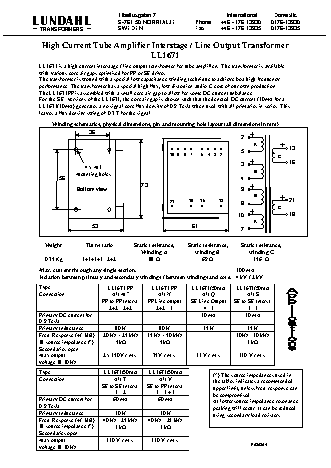
  • Tibeliusgatan 7                        International   Domestic
    LUNDAHL                        S-761 50 NORRTALJE         Phone    +46 - 176 13930   0176-13930
    TRANSFORMERS                 SWEDEN                     Fax      +46 - 176 13935   0176-13935
    High Current Tube Amplifier Interstage / Line Output Transformer
    LL1671
    LL1671 is a high current interstage / line output transformer for tube amplifiers. The transformer is available
    with various core air gaps optimised for PP or SE drives.
    The transformer is wound with a special low capacitance winding technique to achieve best high frequency
    performance. The transformer has a special high flux, low distortion audio C-core of our own production.
    The LL1671PP is assembled with a small core air gap to allow for some DC current unbalance.
    For the S.E. versions of the LL1671, the core air gap is chosen such that the denoted DC current (30mA for a
    LL1671/30mA) generates a no signal core flux density of 0.9 Tesla when used with all primaries in series. This
    leaves a flux density swing of 0.7 T for the signal.
    Winding schematics, physical dimensions, pin and mounting hole layout (all dimensions in mm)
    36
    2
    A
    5                13
    10   9   8   7   5   4   3   2         C
    3                16
    4 x M3
    Mounting holes                                                   B
    56                                                                4
    73
    Bottom view                                                9
    B
    21     18   16    13                       21
    8
    C
    10                18
    A
    53                                  61
    7
    Weight         Turns ratio      Static resistance,     Static resistance,     Static resistance,
    Winding A          winding B           winding C
    0.75 Kg       1+1+1+1 : 2+2          88 W                69 W              156  W
    Max. current through any single section:                               100 mA
    Isolation between primary and secondary windings / between windings and core:  4 kV / 2 kV
    Type                     LL1671 PP      LL1671 PP      LL1671/30mA     LL1671/30mA
    Connection                Alt M??          Alt N           Alt Q           Alt S
    PP to PP Interst.    PP Line output   SE Line Output   SE to SE Interst.
    2+2 : 2+2        2+2 : 1          4 : 1           1 : 1
    Primary DC current for       -               -            30 mA           30 mA
    0.9 Tesla
    Primary Inductance         80 H            80 H            35 H            35 H
    Freq. Response (+/-1dB)   20 Hz – 25 kHz    15 Hz – 50 kHz             30Hz - 30 kHz
    @ source impedance (*)      5kW             5kW                            3 kW
    Secondaries open
    Max output             2 x 150V r.m.s.   75V r.m.s.      33 V r.m.s.    130 V r.m.s.
    voltage @ 30 Hz
    Type                   LL1671/30mA     LL1671/30mA             (*) The source impedances used in
    Connection                 Alt T           Alt V               the tables indicates a recommended
    SE to SE Interst.   SE to PP Interst.   upper limit, unless freq. response can
    1 : 2         1 : 1 + 1            be compromised.
    Primary DC current for     60 mA           60 mA               At lower source impedance resonance
    0.9 Tesla                                                      peaking will occur. It can be reduced
    Primary Inductance         10 H             10 H               using secondary load resistors.
    Freq. Response (+/-1dB)   40 Hz - 25 kHz   40 Hz - 25 kHz
    @ source impedance (*)     1 kW             1 kW
    Secondaries open
    Max output              130 V r.m.s.     130 V r.m.s.
    voltage @ 30 Hz                                                             R030304
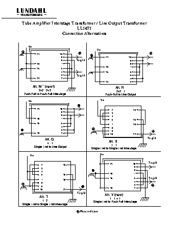
  • LUNDAHL
    TRANSFORMERS
    Tube Amplifier Interstage Transformer / Line Output Transformer
    LL1671
    Connection Alternatives
    V+
    V+
    21              10
    9                               21              10
    8          To grid                               9
    18               7                                                8
    18               7
    16               5
    4                               16               6
    3          To grid                               5
    13               2                                                4
    13               3
    Alt. M?? (new!)                                           Alt. N
    2+2 : 2+2                                              2+2 : 1
    Push-Pull to Push-Pull Interstage                        Push-Pull to Line Output
    V+                                                 V+
    21              10                                   2              13
    9                                   3
    8                                   4
    18               7
    5              16
    16               5                                   7              18
    4                                   8
    3                                   9
    13               2                                  10              21
    To grid
    Alt. Q                                       Alt. S
    4 : 1
    1 : 1
    Single End to Line Output                Single End to Single End Interstage
    V+
    V+
    To grid
    2              13                                21              10
    3                                                                 9
    4                                                                 8
    5              16                                18               7
    7              18                                16               5         To grid
    8                                                                 4
    9                                                                 3
    10              21                                13               2
    To grid             Alt. V (new)
    Alt. T                                            1 : 1 + 1
    1 : 2                               Single End to Push Pull Interstage
    Single End to Single End Interstage
    Phase Indicator

Скачать инструкцию

Файл скачали 11 раз (Последний раз: 06 Декабря 2022 г., в 23:06)

Загрузить

Инструкции к похожим моделям