На сайте 123387 инструкций общим размером 499.28 Гб , которые состоят из 6234324 страниц
Фото
Руководство пользователя LUNDAHL LL1660S. Основные функции, характеристики и условия эксплуатации изложены на 2 страницах документа в pdf формате.
Доступно к просмотру 2 страницы. Рекомендуем вам скачать файл инструкции, поскольку онлайн просмотр документа может сильно отличаться от оригинала.
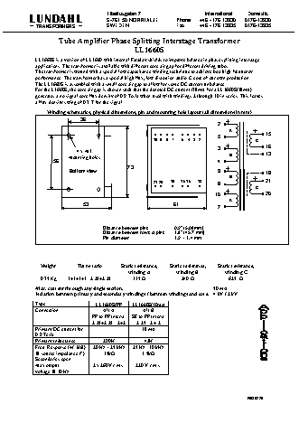
Tibeliusgatan 7                        International   Domestic
LUNDAHL                        S-761 50 NORRTALJE         Phone    +46 - 176 13930   0176-13930
TRANSFORMERS                 SWEDEN                     Fax      +46 - 176 13935   0176-13935
Tube Amplifier Phase Splitting Interstage Transformer
LL1660S
LL1660S is a version of LL1660 with internal Faraday shields to improve balance in phase splitting interstage
applications. The transformer is available with different core air gap for different driving tubes.
The transformer is wound with a special low capacitance winding technique to achieve best high frequency
performance. The transformer has a special high flux, low distortion audio C-core of our own production.
The LL1660S is assembled with a small core air gap to allow for some DC current unbalance.
For the L1660S, the core air gap is chosen such that the denoted DC current (18mA for a LL1660S/18mA)
generates a no signal core flux density of 0.9 Tesla when used with windings 2 through 10 in series. This leaves
a flux density swing of 0.7 T for the signal.
Winding schematics, physical dimensions, pin and mounting hole layout (all dimensions in mm)
36
2
A
5                  15
10   9   8   7   5   4   3   2           C
3                  16
4 x M3                                                                     13
Mounting holes                                                   B
56                                                                4
73
Bottom view                                                9                  18
B
21 20   18   16 15   13                      21
8
C
10                  20
A
53                                  61
7
Distance between pins       0.2” (5.08mm)
Distance between rows of pins   1.8” (45.7 mm)
Pin diameter                1.2  - 1.4 mm
Weight         Turns ratio      Static resistance,     Static resistance,     Static resistance,
winding A          winding B           winding C
0.75 Kg    1+1+1+1 : 2.25+2.25       315 W              240 W              625  W
Max. current through any single section:                               50 mA
Isolation between primary and secondary windings / between windings and core:  4 kV / 2 kV
Type                    LL1660S/PP    LL1660S/10mA
Connection                 Alt A           Alt B
PP to PP Interst.   SE to PP Interst.
2.25+2.25 : 2+2   2.25 : 2 + 2
Primary DC current for       -            18 mA
0.9 Tesla
Primary Inductance         290H             42H
Freq. Response (+/-1dB)   20 Hz – 25 kHz    25 Hz - 30 kHz
@ source impedance (*)      15kW           3.5kW
Secondaries open
Max output             2 x 260V r.m.s.   220 V r.m.s.
voltage @ 30 Hz
R030220
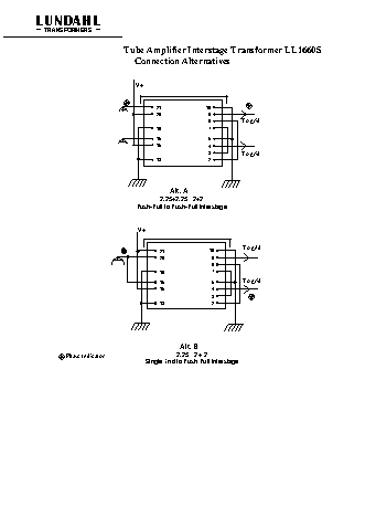
LUNDAHL
TRANSFORMERS
Tube Amplifier Interstage Transformer LL1660S
Connection Alternatives
V+
21              10
20               9
To grid
8
18               7
16               5
15               4
3          To grid
13               2
Alt. A
2.25+2.25 : 2+2
Push-Pull to Push-Pull Interstage
V+
21              10         To grid
20               9
8
18               7
16               5         To grid
15               4
3
13               2
Alt. B
Phase Indicator                     2.25 : 2 + 2
Single End to Push Pull Interstage