На сайте 123418 инструкций общим размером 499.4 Гб , которые состоят из 6235582 страниц
Фото
Руководство пользователя LUNDAHL LL1544A. Основные функции, характеристики и условия эксплуатации изложены на 2 страницах документа в pdf формате.
Доступно к просмотру 2 страницы. Рекомендуем вам скачать файл инструкции, поскольку онлайн просмотр документа может сильно отличаться от оригинала.
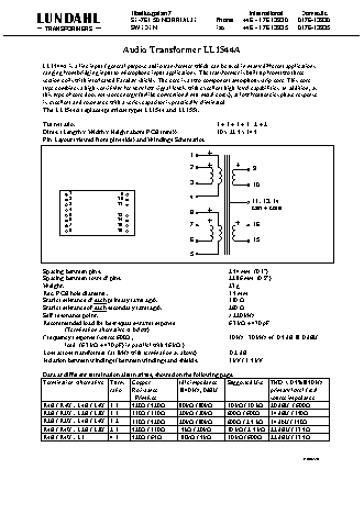
Tibeliusgatan 7                        International    Domestic
LUNDAHL                        SE-761 50 NORRTALJE        Phone     +46 - 176 13930   0176-13930
TRANSFORMERS                SWEDEN                     Fax       +46 - 176 13935   0176-13935
Audio Transformer LL1544A
LL1544A is a line input / general purpose audio transformer which can be used in many different applications
ranging from bridging input to microphone input applications. The transformer is built up from two three-
section coils with interleaved Faraday shields. The core is a two-component amorphous strip core. This core
type combines a high sensitivity for very low signal levels with excellent high-level capabilities. In addition, as
this type of core does not store energy (unlike conventional mu-metal cores), at low frequencies phase response
is excellent and resonance with a series capacitor is practically eliminated.
The LL1544A replaces previous types LL1544 and LL1554.
Turns ratio:                                             1 + 1 + 1 + 1 : 2 + 2
Dims: (Length x Width x Height above PCB (mm))           30 x 22.5 x 14.5
Pin Layout (viewed from pins side) and Windings Schematics:
1
2                    9
3                    10
1                9
2               10                     4                    11, 13, 14
3              11                                           can + core
4
5              13                      8
6              14
7              15                      7                    16
8
16
6                    15
5
Spacing between pins:                                        2.54 mm  (0.1")
Spacing between rows of pins:                                22.86 mm  (0.9")
Weight:                                                      27 g
Rec. PCB hole diameter:                                      1.5 mm
Static resistance of each primary (average):                 130 W
Static resistance of each secondary (average):               260 W
Self resonance point:                                        > 220 kHz
Recommended load for best square-wave response               6.7 kW + 470 pF
(Termination alternative A below):
Frequency response (source 600W ,                            10 Hz - 70 kHz +/- 0.5 dB @ 0 dBU
load  (6.7 kW + 470 pF) in parallel with 56 kW ):
Loss across transformer (at 1kHz with termination as above):    0.2 dB
Isolation between windings / between windings and shields:   3 kV / 1.5 kV
Data at different termination alternatives, showed on the following page:
Termination Alternative   Turns  Copper      Idle impedance   Suggested Use  THD < 0.5%@50 Hz
ratio   Resistance     @40 Hz, 0dBU                  primary level / real
Prim/sec                                    source impedance
R4B / R4U : L4B / L4U  1:1   520W / 520W     80kW / 80kW    10 kW / 10 kW  20 dBU  / 600W
R2B / R2U : L2B / L2U  1:1   130W / 130W     20kW / 20kW    600W / 600W    14 dBU / 150W
R2B / R2U : L4B / L4U  1:2   130W / 520W     20kW / 80kW    600W / 2.5 kW  14 dbU / 150W
R4B / R4U : L2B / L2U  2:1   520W / 130W      5kW / 20kW    10 kW / 2.5 kW  22 dBU / 37.5W
R4B / R4U : L1        4:1    520W / 65W       80kW / 5kW    10 kW / 600W   22 dBU / 37.5W
.
R030220
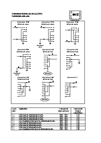
9        1
Connection alternatives for LL1544A                                  10        2
3
11
4
Component side view                                                  13        5
14
6
15        7
8
16
Component side view
Connection: R4B             Connection: R4U              Connection: R2B
Balanced source             Unbalanced source             Balanced source
9                               9                            9
10                              10                           10
11                              11                           11
13                              13                           13
14                              14                           14
15                              15                           15
16                              16                           16
Grounded at
source
Connection R2U               Connection L4B               Connection L4U
Unbalanced source              Balanced load               Unbalanced load
9                1                         1
10                2                         2
11                3                         3
4                         4
13                5                         5
14                6                         6
15                7                         7
16                8                         8
Grounded at                          Centertap
source
Connection L2U               Connection L2B               Connection L1
Unbalanced load               Balanced load
1                            1                          1
2                            2                          2
3                            3                          3
4                            4                          4
5                            5                          5
6                            6                          6
7                            7                          7
8                            8                          8
Centertap
Turns   Application                                     Transformer      Transformer
ratio                                                 Input (primary)      Output
(secondary)
1:1     Line input to unbalanced circuits               R4B / R4U           L4U
1:2     Line input to unbalanced circuits               R2B / R2U           L4U
2:1     Line input to unbalanced circuits               R4B / R4U           L2U
1:1     Low impedance line input to unbalanced circuits   R2B / R2U         L2U
1:1     Line input to balanced circuits                 R4B / R4U           L4B
1:2     Line input to balanced circuits                 R2B / R2U           L4B
2:1     Line input to balanced circuits                 R4B / R4U           L2B
1:1     Low impedance line input to balanced circuits   R2B / R2U           L2B