На сайте 123387 инструкций общим размером 499.28 Гб , которые состоят из 6234324 страниц
Фото
Руководство пользователя FELISATTI RF12/710. Основные функции, характеристики и условия эксплуатации изложены на 31 странице документа в pdf формате.
Доступно к просмотру 28 страниц. Рекомендуем вам скачать файл инструкции, поскольку онлайн просмотр документа может сильно отличаться от оригинала.
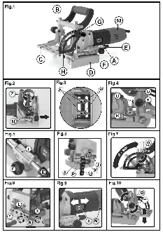
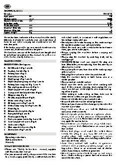
TECHNICAL DATA
Doweler                                                                 RF12/710
Input power       W                                                         710
No-load speed     r.p.m.                                                  18500
Distance between bits   mm                                                   32
Inclination angle                                                          0-90?
Perforation depth   mm                                                     0-37
Maximum O for bits   mm                                                      12
Minimum O for bits   mm                                                      6
Approx. weight    Kg.                                                       3.6
The instructions contained in this manual must be strictly   mal cutout switch, in accordance with regulations  on
followed, it should  be carefully read  and kept close  at   low-voltage wiring sitemaps.
hand  to use when carrying out maintenance on the   ? Do not pierce the motor housing as this could damage
indicated parts.                          the double insulation (use adhesive labels).
If the tool is used with care and normal maintenance is   ? Check the work area with a metal detector for hidden
carried out, it will work well for a long time.   wires, gas and/or water pipes.
The functions and use of the tool you have bought shall   ? Always unplug  the machine  before carrying  out
be only those described in this manual. Any other use   work on it.
of the tool is strictly forbidden.      ? Always  stop the machine by switching it off, not by
unplugging it.
ILLUSTRATIONS
? WARNING! Before each  use, inspect  the plug  and
DESCRIPTION (See figures)                 lead. Should they need replacing, have this done by an
official service centre.
A  On/Off switch (Fig.1 and 9)          ? Always keep the mains lead clear of the working range
B  Auxiliary handle (Fig.1)               of the machine.
C  Folding base (Fig.1)                 ? Only plug the machine in when it is switched off.
D  Frontal base (Fig.1)                 ? Hold the machine firmly in both hands and in  a
E  Depth gauge (Fig.1 and 5)              stable position.
F   Depth stop fixing wing nut (Fig.1 and 5)   ? Always work on a stable surface.
G  Folding base wing nut (Fig.1 and 7)   ? Make sure  the vents  are free  when working  with
H  Flip angle graduated scale (Fig.1)     dust.  If they  require cleaning, first  unplug the ma-
I   Depth adjustment scale (Fig.5)        chine, do not use metal objects and avoid  damag-
J   Transparent frontal protection (Fig.6)   ing internal parts.
K  Stepped stop (Fig.4)                 ? When drilling in walls ceiling,  or floor, take care  to
avoid electric cables and gas or water pipes.
L   Flexibly adjustable pin (Fig.8)
M  Motor cover (Fig.1 and 9)            ? Never cut metallic items, for example nails.
? Ensure that the item is free of foreign bodies.
N  Bit fixing screw (Fig.2 and 3)       ? Never put your hands in the shavings ejector when the
O  Vertical stop wing nut (Fig.4 and 10)   machine is in motion.
P Pivot (Fig.6)                         ? Keep work area clean  and well lit.  Cluttered and
Q  Bit diameter template (Fig.6)          dark areas invite accidents.
R  Fixing bolt (Fig.6 and 8)            ? Do  not operate power  tools in explosive atmos-
S  Pivot support (Fig.6)                  pheres, such as in the presence of flammable liq-
T   Rack and pinion knob (Fig.4 and 10)   uids, gases or dust. Power tools create sparks which
U  Turret adjustment screw (Fig.4)        may ignite the dust or fumes.
W  Tool carrier (Fig.3)                 ? Keep-children  and bystanders  away while oper-
X  Stud adjustment screw (Fig.8)          ating a power tool. Distractions can cause you to
Z   Screwdriver (Fig.2 and 8)             lose control.
? Power  tool plugs must  match the outlet. Never
EQUIPMENT                                 modify the plug  in any way.  Do not use  any
adapter plugs with earthed (grounded)  power
- Operating instructions                  tools. Unmodified plugs and matching outlets wilt re-
- Safety instructions                     duce risk of electric shock.
- Warranty
? Avoid body contact with earthed or grounded
SAFETY INSTRUCTIONS                       surfaces such as pipes, radiators, ranges and re-
frigerators.  There is an increased risk of electric
? Please  see  “Safety Instructions” manual, supplied   shock if your body is earthed or grounded.
with this instruction manual.          ? Do not expose  power tools  to rain  or wet  condi-
? For your personal safety, always connect the machine   tions. Water entering  a power tool  will increase  the
to a mains supply protected by a differential and ther-
risk of electric shock.
? Do  not abuse  the cord.  Never use  the cord for   STARTING THE TOOL
carrying, pulling or  unplugging the power  tool.   WARNING! Check that the mains voltage is the same as
Keep cord away from  heat, oil, sharp edges  or   that in the machine’s specifications.
moving parts. Damaged or entangled cords increase   Plug the machine in with the switch off.
the risk of electric shock.
? When  operating a power  tool outdoors, use an   Start the machine  by turning the  switch to position  1
("on"). To switch off, do the same in reverse.
extension cord  suitable for  outdoor use. Use of
cord suitable for outdoor use reduces the risk of elec-  CHANGING BITS
tric shock.                            PRECAUTION: The machine should always  be
? Stay alert, watch what  you are doing and  use   unplugged before making any adjustments to  the
common sense when  operating a  power tool.  Do   machine.
not use a power tool while you are tired or under   Use highly sharpened bits to ensure a clean cut.
the  influence of drugs, alcohol or medication.  A
moment of inattention while operating power tools may   - Set the tool fitting with the (N) screws facing upwards
(Fig.2 and 3).
result in serious personal injury.     - Loosen the screws using the screwdriver (Z).
? Use safety equipment. Always wear eye protection.   - Remove the bit pulling outwards.
Safety equipment such as dust mask, non-skid safety   - Insert  the new bit in the fitting and adjust the fixing
shoes, hard hat, or hearing protection used for appro-  surface so that it  can be secured  in place using  the
priate conditions will reduce personal injuries.   screws.
? Do not overreach.  Keep proper  footing and  bal-  - Fix the bits by tightening the screws.
ance at all  times.  This enables  better control of  the   - Ensure the bits are correctly fitted.
power tool in unexpected situations.   The  pre-selection of the screw depth will be changed
? Store idle power tools out of the reach of children   and you will have to readjust the limit.
and do not allow persons unfamiliar with the   - Loosen wing nut (F) (Fig.5).
power tool or these instructions to operate  the   - Fully open folding base (C).
power tool. Power tools are dangerous in the hands   - Retighten wing nut (F).
of untrained users.                    - Place the machine in position.
? Maintain power tools. Check for misalignment or   - Move the motor cover (M) forward until it comes into
binding of moving parts, breakage of parts and any   contact with the tip of the bit.
other  condition that may affect the power tools   - Loosen the wing nut (F) and insert the depth stop (E)
operation.  If damaged,  have the  power tool re-  then tighten the wing nut (F).
paired before  use. Many accidents are caused by   - Adjust the scale to zero (I).
poorly maintained power tools.
? Use the power tool, accessories and tool bits etc.,   BITS ADJUSTMENT
in accordance with these instructions and in  the   Adjusting the perforation depth (Fig.5)
manner intended for the particular type of power   - Loosen wing nut (F).
tool, taking into  account the working  conditions   - Adjust the depth stop (E) to the selected level.
and the work to be performed. Use of the power tool   - Tighten the wing nut (F).
for operations different from intended could result in a
hazardous situation.                   Adjusting the inclination angle (Fig.7)
The folding base  (C) can  be adjusted  continuously
BRIEF DESCRIPTION                       between 0? and 90?.
To facilitate rapid adjustments there are three set posi-
This tool can only be used to perforate solid wood
and compound materials, such as agglomerated   tions:  22.5?, 45? and 67.5?.
wood, stratified wood boards and Mdf boards,  using   - Loosen the wing nut (G).
the adequate bits.                      - Adjust  the folding base  (C)  to the selected angle
Any alternative use of the machine would be consid-  and in accordance with the scale  (H) indicated  on
the base.
ered inappropriate and no  claims can be  made   - Tighten the wing nut (G).
against the  manufacturer for  damages arising  from
inappropriate use, the user assuming full, sole  re-  Adjusting the distance between perforation borders.
sponsibility in this case.              - Loosen the wing nut (O) (Fig.4 and 10).
- Adjust the folding  base  (C) to  the selected  level, ac-
BEFORE USING THIS TOOL                    cording to the scale.
Before  using the tool,  make sure the  mains voltage is   - Move the stop up or down using the notched knob and
correct: it must be the same as that on the specification   T pinion until it reaches the desired height.
label. Machines with 230V can also be connected to a   - Tighten the wing nut (O).
220-V mains supply.                     Using the stepped stop  (K), different defined  distance
Ensure the bits are correctly assembled.   intervals can be set.
To work with a single bit, remove the stud bolt from the   - Loosen the nut on the turret adjustment screw (U).
free fitting.                           - Raise the turret adjustment screw until it protrudes
from the turret.
Wherever possible, set the object so it cannot move.   - Fix the stop  at the  necessary height  by following  the
Wood dust reduces visibility and could be noxious. The   instructions in the section Adjusting the Height of the
machine must be connected to a suction system.   Stop further back.
- Lower the turret adjustment screw until it comes into ACCESSORIES contact with the turret. - Tighten the nut on the turret adjustment screw. Accessories and their corresponding order number can be found in our catalogues. Note: The turret has 4 fixed positions which can be adjusted to any position of the guide. Each position is in MAINTENANCE AND CARE increments of 3 mm and is calibrated by the manufac- turer with the settings indicated on the label. WARNING! Always unplug the machine before carrying out work on it. INSTRUCTIONS FOR CHANGING THE TEMPLATE (Fig.6) - Inspect the mounting screws: Regularly inspect all the mounting screws and ensure they are firmly Adjusting the studs. tightened. Should any screw be loose, tighten it 1. Remove the bit and instead put the pivot (P). immediately. Failure to do so could put you at se- 2. Loosen the fixing bolt (R). rious risk. 3. Place the template (Q) and set it to position depend- - Motor maintenance: Always take the greatest care ing on the bit diameter being used. over this and make sure that the motor winding is 4. Manually tighten the pivot support (S) until it hits the not damaged and does not become wet with oil or stop and tighten the fixing bolt (R). water. 5. Remove the template (Q) and the pivot (P) and place - The vents should always be kept clean and free of the corresponding drill bit. obstacles. 6. Repeat the same operation on the second bit. - Clean the machine thoroughly after each use. Blast the PERFORATING ACCORDING TO COURSE LINES motor regularly with compressed air. - Check that the mains lead is in good condition. If it is On the folding base (C) there are three marks of which the right and the left correspond to the centre not, take it to an Official Service Centre to have it of the bits. replaced. - Position the machine over the object and adjust it with - Brush replacement: Brushes must be replaced the help of the markers. when length reaches 8 mm or less. To do so, - Position the rotating stop over the object with your free please contact an authorized after sales service hand. center. We recommend that every other time you take a tool to an after sales service centre for brush - Start up the machine and push the motor cover (M) replacement, you also order a general service forwards until it hits the stop. (cleaning and lubrication). - Remove the motor cover (M) and disconnect the machine. - Use only Felisatti accessories and spares. Parts the changing of which is not covered in this instruction PERFORATING WITH THE ADJUSTMENT PIN (Fig.8) manual, should be replaced in a Felisatti Official Ser- vice Centre (See Warranty/Official Service Centre ad- The base (D) has two flexibly adjustable pins (L) dress leaflet). allowing perforations be made while maintaining a fixed distance between the outside border of the object being worked on. The machine can be posi- Do not dispose of electric tools in tioned to the left or right of the object to be worked the household waste! on as required. - Place the machine over the object to be worked on, inserting one of the pins (L) and positioning another on the outside border. - Place the folding base (C) on the object to be worked In accordance with European Directive 2002/96/EC on, start up the machine and push the motor cover (M) relating to old electrical and electronic appliances and forward until it reaches the stop. its translation into national law, used electric tools must - Remove the motor cover (M) and disconnect the be collected separately and recycled in an ecologically machine. desirable way. DUST EXTRACTION WARRANTY WARNING! Always make sure that the tool is switched See general warranty conditions printed on the attached off and unplugged before fitting or removing any dust sheet. extraction device. Dust extraction keeps the workplace clean, prevents NOISE AND VIBRATION dust build-up in the air and facilitates waste elimination. CAUTION: A suction extractor should always be used This tool has been designed and made to reduce noise that has been designed in accordance with the applica- to a minimum. However, in spite of this, in certain ble directives in relation to dust emission. The flexible circumstances the maximum noise level in the place hoses of conventional vacuum cleaners fit directly onto of work could exceed 85 dBA. In this case, the op- the dust extraction nozzle. erator should wear ear protection.