На сайте 123351 инструкция общим размером 499.19 Гб , которые состоят из 6233088 страниц
Фото
Руководство пользователя FELISATTI MTF250/1500T. Основные функции, характеристики и условия эксплуатации изложены на 8 страницах документа в pdf формате.
Доступно к просмотру 5 страниц. Рекомендуем вам скачать файл инструкции, поскольку онлайн просмотр документа может сильно отличаться от оригинала.
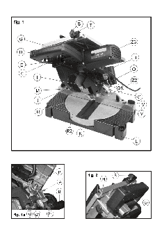
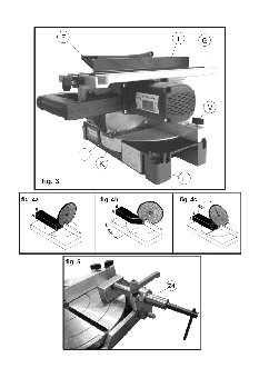
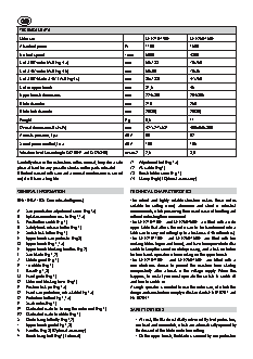
TECHNICAL DATA
Mitre saw                                MTF216/1100T   MTF250/1500T
Absorbed power                     W     1100           1500
No-load speed                      / min  5000          4300
Cut at 90?/mitre (AxB Fig.4 a)     mm    58x133         70x150
Cut at 45?/mitre (AxB Fig.4 b)     mm    58x90          70x85
Cut at 90?/blade at 45? (AxB Fig.4 c)  mm  35x1330      47x150
Cut on upper bench                 mm    31,5           45
Upper bench dimensions             mm    224х358        264х385
Blade diameter                     mm    216            250
Blade hole diameter                mm    20(30)         20(30)
Weight                             Kg    9,5            11
Overall dimensions (LxHxW)         mm    427x277x531    460х450х300
Acoustic pressure, Lpa             dBA   96             92
Sound power emitted, Lwa           dBA   109            105
Vibration level (according to ISO 8041 and ISO 5348)  m/sec2  2,5  3,9
Carefully observe the instructions in this manual, keep it in a safe   Z1  Adjustment bolt (Fig.1a)
place at hand for any possible checks on the parts indicated.  Z2  AC cable (Fig.1)
If the tool is used with care and a normal maintenance is carried   Z3  Brush holder cover (Fig.1)
out, it will have a long life.       Z4  Clamp (Fig.5) (Optional accessory)
GENERAL INFORMATION                  TECHNICAL CHARACTERISTICS
DENTIFICATION (See indicated figures)  The robust  and highly reliable  structure  makes these mitres
suitable  for cutting  wood,  aluminium  and  steel  in  industrial
A   Saw penetration adjustment screw (Fig.1a)  environments, while preserving their usual ease of handling and
B   Uptake connection nozzle (Fig.1,1a)  without restricting their movement.
C   Pushbutton switch (Fig.1)        The MTF216/1100T  and MTF250/1500T are fitted with a wide
D   Safety hook release button (Fig.1)  upper table that allows the mitre saw to be transformed into a
E   Switch lock button (Fig.1)       table saw to carry out cutting (up to a thickness of 45 millimetres).
F   Upper bench saw protector (Fig.3)   The  MTF216/1100T    and  MTF250/1500T  are  fitted  with  two
G   Upper bench (Fig.1,1a)           working tables (upper and lower), and have been provided with a
H   Upper bench blocking handles (Fig.2)  switch to keep the circuit on while pressing, and a lock-on button
I   Saw blade (Fig.1,2)              for free-hands operation when working on the upper bench.
J   Mobile guard (Fig.1)             The  MTF216/1100T    and  MTF250/1500T  are  fitted  with  a
K   Turntable (Fig.1)                new electronic  device to prevent the machine from starting
L   Base (Fig.1,3)                   unexpectedly after a break in the voltage supply.  When this
M  Fixed guide (Fig.1)               happens, to restart you must oper-ate the switch to switch-off
O   Motor unit blocking lever (Fig.1)  and then to switch-on.
P   Position lock pin (Fig.1a)       A single operator is needed to use the mitre saw, of which the
Q   Fixed saw protection, extractable (Fig.1а)  design and construction comply with stan-dards EN 61029-1 and
Q1  Protection button (Fig.1,1a)     EN 60204-1.
R   Scale index (Fig.1)
R1  Graduated scale for turning the motor unit (Fig.1)  SAFETY DEVICES
R2  Graduated scale turntable (Fig.1)
S   Guide fixing butterfly (Fig.1,2)   •  At rest, the blade is totally covered by two protec-tors,
T   Upper bench guide (Fig.1,3)        one fixed and one mobile, which are automati-cally opened by
V   Handles (Fig.3) (Optional accessory)  the descent of the blade unit when cutting.
Y   Bench fixing bolt (Fig.1) (internal)  •  On the upper bench, the blade is covered by one protection
which is raised by the work when it comes close to the cut.  MITRE SAW ADJUSTMENT - SQUARING
WARNING – these protectors must not be removed, in order
to prevent danger for the operator.  The mitre is delivered by the manufacturer already adjusted and
•  In  the  event  that  the  switch  lock  button  has  not  been   squared according to standard pa-rameters.
engaged,  the machine  will  stop  automatically  when the   WARNING  –  before  making  any  adjustment  of  the  mitre,
handgrip is released.               unplug the machine.
WARNING –  engaging  the  lock  button  disables the  safety   1. BLADE UNIT LIFTING
device  provided  by  the  manufacturer  and  enables  push-  An internal spring keeps the motor unit at rest position (raised).
button start. It is recommended that this device be used with   In this position, a safety hook prevents the unit from being
the utmost caution.                  activated accidentally.
The tool has been designed and built so that it is possible to   1.1 To unlock the motor unit and to be able to use the machine as
work in all  situations with total safety, however, in special working   a mitre saw, activate the front button D (Fig.1) (the operation may
conditions, gloves and protective goggles should be worn.  be carried out with the right hand on the handle).
The tool has been designed and built to reduce noise to a   1.2. To use the machine as a bench circular saw, unlock the
minimum (see technical data), however, in special conditions the   motor unit as indicated in 1.1, and after lowering it completely,
maximum noise level in the workplace might exceed 85 dB(A).   block it with pin P (Fig.1a).
In this case, the operator should protect himself from excessive   2. BLADE PENETRATION ADJUSTMENT
noise by using ear protectors.       The depth of penetration has already been adjusted by the
manufacturer during testing.
GENERAL SAFETY REGULATIONS           As incorrect adjustment may cause sharpness to be lost quickly
and/or the teeth of the blade to be broken, further adjustment
See manual “Safety instructions” which is supplied together   might be needed, in which case it will be necessary to work as
with this instructions manual.       follows:
-  Activate bolt A (Fig.1а) and the corresponding lock nut to
INSTALLATION                           create a lower limit for the motor housing ideal for preventing
the blades from coming into contact with the turntable.
1. ELECTRICAL CONNECTION             WARNING – once for this operation is complete, make sure
Before connecting the machine to the mains, one must make sure   that the blade is NOT in contact with the turntable and that
that it complies with current regula-tions in the country where it is   the lock nut is tightened.
used and that the voltage and frequency are as indicated on the   3. TURNTABLE ADJUSTMENT
char-acteristics plate.              0? Regulation (Fig.3)
When extensions are used, make sure that the cross section of   -  Lower the head of the machine and lock with pin P (Fig.1a).
the cables is suited to their length. If using roll up extensions,   -  Set the turntable to zero.
make sure that they unroll completely in order  to prevent   -  Loosen the handles  V, remove the guides  X – Optional
overheating.                           accessory and loosen bolts Y.
WARNING – before plugging in the machine, make sure that   -  Set a square between the saw blade and guide M (Fig.1).
the switch lock button is released.    -  Keeping the turntable at zero, move the guide to 90? on the
2. WORKPLACE                           square.
The tool that you have purchased is a transportable or semi-  -  Tighten bolts Y, assemble guides X and adjust handles V –
stationary electric tool. Only one operator is needed to use it,   optional accessory.
given its structure, weight and ease of handling.  4. ADJUSTING  THE  SAW BLADE  WITH RESPECT  TO  THE
In normal use, the operator is in front of the machine with the   WORKING PLANE
handle to his right.  The right hand on the handle allows the   90? adjustment (Fig.2)
machine to be handled completely, in fact, the switch and a safety   -  Lower the head of the machine and lock with pin P (Fig.1a)
hook may be accessed without releasing the handle.  -  Place a square between the base and the saw blade.
-  Loosen lever O and adjust with bolt Z.
CONSTANT ELECTRONICS                   -  Tighten the lock nut well to make sure that the position is
fixed and tighten lever O.
The built-in module permits:         5. VERTICAL PLANE  LIMIT STOP  ADJUSTMENT (0? - 45?)
-   Soft start.                      (Fig.2)
-   The maintenance of a practically constant rated speed up to   -  Lower the head of the machine and lock it with pin  P
rated power.                           (Fig.1a).
-   An overload protection system by means of current cut-off   -  Set the turntable to zero and lock.
in the case of motor overload, in which case the burring machine   -  Set the head to 45? and lean a 45? square between the base
shuts down and re-starts when the grinding pressure has been   and the saw blade.
reduced.                               -  Loosen lever O and adjust using bolt Z.
-  Regulate the 45? using bolt Z1 (Fig.1a), after releasing the
lock nut.
-  Tighten the lock nut to make sure that the position does not   upper plane, proceeding to lock the handles once more.
change.                             7. USE OF THE STOP GUIDE FOR THE UPPER BENCH (Fig.7)
Use as follows:
OPERATION AND USE                      -  Insert guide T in the upper bench.
-  Select the cutting width.
1. CUTTING WITH  THE BLADE  AT 90?  AND  TURNTA-BLE   -  Lock guide T by tightening butterfly U followed by butterfly
TURNED                                 S.
-  Unlock the turntable K (Fig.1) by turning lever Y to the left.  8. MISCELLANEOUS ACCESSORIES
-  Turn the turntable  with the handle,  selecting  the cutting   The machine is supplied with the uptake nozzle included  B
angle required using the graduated scale  R2 and index  R   (Fig.1) and may therefore be connected easily to any vacuum
(Fig.1), and lock again by turning lever Y (Fig.1) to the right.   cleaner.
Note: there are pre-set cutting angles (0?, ±15?, ±22?30’, ±30?,   9. MISUSE
±45?) on which the turntable may easily be locked.  The functions and use of the tool that you have bought are only
2. CUTTING WITH THE BLADE INCLINED AND TURNTABLE   as indicated in this manual.
AT 0? (Fig.6) (Optional accessory)   Any other use of the tool is entirely prohibited.
-  Move guide X outwards, in the direction of the arrow, or   •  Do not cut aluminium or steel on the upper plane.
even out of the machine for better operation. -   R e l e a s e   •  Always use sharp blades suitable for the cut to be made.
the motor unit by loosening lever O (Fig.1).  •  Do not use the machine without the described protection.
-  Turn the motor unit, selecting the required inclination using   •  Not suitable for foodstuffs.
the graduated scale R1 (Fig.1) and lock lever O once more.  •  Use the machine only for cutting wood, aluminium profiles,
3. USE OF THE MITRE SAW                PVC tubes, steel pipes and only with the right blade.
WARNING – Make sure that the lock button E (Fig.1) is in the   The cutting of any other material is entirely prohib-ited.
release position.
-  Set the upper bench to the maximum height.  MAINTENANCE
-  Always start with the motor unit in rest position (raised with
the safety hook fitted)             WARNING - before any maintenance operation, unplug the
-  Fix the material to be cut firmly to the cutting plane.  machine.
-  Start and wait for the blade to reach maximum revolutions.  1. LUBRICATION
-  Press the button releasing the motor unit.  The mitre saw is delivered with in all moving parts of the motor
-  Gradually lower the motor unit and cut.  and gearbox entirely lubricated and needs no further lubrication
4. BLADE START AND STOP              operations.
WARNING – make sure that the moving protector is in the correct   Regular lubrication is recommended of the joints of the moving
position when the blade is at rest (raised).  controls.
The machine is provided with a switch C (Fig.1) with push button,   2. ORDINARY CLEANING
which is used to start and stop the blade. It is possible to block   WARNING - avoid touching the handle with hands dirty with
the switch ‘ON’ by pressing the lock button E (Fig.1)  oil or grease. In such an event, clean immediately.
WARNING – engaging the lock button disables the safety   -  Carefully clean the machine after use with dry com-pressed
device  provided  by  the  manufacturer  and  enables  push-  air.
button start. It is recommended that this device be used with   3. DISPOSAL
the utmost caution and ONLY when using the machine as a   When the life of the machine is at an end or when it can no
circular saw.                        longer be repaired, make sure that the scrap is disposed of in
To release the switch again, it is only necessary to press the   observance of current regulations in the country of use and that
button and release.                  the operation is undertaken by specialised personnel authorised
5. USE OF THE CLAMP (OPTIONAL ACCESSORY)  in the matter.
-  Raise the saw to be able to place the wood board or the
aluminium pipe on the bench for cutting and in position with   PART REPLACEMENT
respect to guide M (Fig.1).
-  Fit the clamp Z4 (Fig.5) if it is not already fitted, and turn the   WARNING  –  before  carrying  out  any  replacement,  unplug
bolt until the clamp press firmly on the piece to be cut, making   the machine.
sure that it do not move, to avoid any accident.  1. REPLACING THE SAW BLADE I (Fig.1)
-  Once the operation is complete, loosen the clamp to release   Replace as follows:
the piece and change the position for the next job.  -  Set the head to fully open (Fig.1)
6. USE OF THE UPPER BENCH              -  Raise the upper bench as far as is allowed.
To use the upper plane, proceed as follows:  -  Release the moving protection Q (Fig.2) working on button
-  Make sure that the lock button E (Fig.1) is released   Q1 (Fig.1a) and raise completely.
(standing out).                       -  Fit the spanner provided in the holes of the clamp, keeping
-  Lower the blade unit completely and lock with pin P (Fig.1a).  the shaft locked with another tubular spanner supplied by the
-  Release  handles  H (Fig.2) and select  the height of the   manufacturer, and unscrew the left bolt until the saw blade is