На сайте 123413 инструкций общим размером 499.36 Гб , которые состоят из 6235398 страниц
Фото
Руководство пользователя NEC Wall Mount PDW T XL. Основные функции, характеристики и условия эксплуатации изложены на 7 страницах документа в pdf формате.
Доступно к просмотру 7 страниц. Рекомендуем вам скачать файл инструкции, поскольку онлайн просмотр документа может сильно отличаться от оригинала.
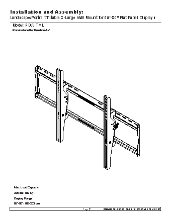
Installation and Assembly:
Landscape/Portrait Tiltable X-Large Wall Mount for 65”-80” Flat Panel Displays
Model: PDW T XL
Manufactured by Peerless-AV
Max. Load Capacity:
225 lbs (102 kg)
Display Range:
65”-80” (165-203 cm)
1 of 7         ISSUED: 2013-07-02   SHEET #: 125-9459-1 2013-07-02
WARNING
• Do not begin to install your product until you have read and understood the instructions and warnings contained in
this Installation Sheet. If you have any questions regarding any of the instructions or warnings, for US customers
please call customer care at 1-800-865-2112, for all international customers, please contact your local distributor.
• This product should only be installed by someone of good mechanical aptitude, has experience with basic building
construction, and fully understands these instructions.
• Make sure that the supporting surface will safely support the combined load of the equipment and all attached
hardware and components.
• Never exceed the Maximum Load Capacity (See page one).
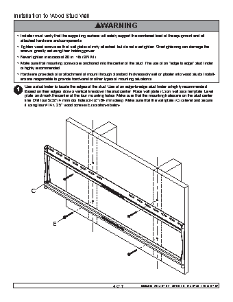
• If mounting to wood wall studs, make sure that mounting screws are anchored into the center of the studs. Use of
an "edge to edge" stud finder is highly recommended.
• Always use an assistant or mechanical lifting equipment to safely lift and position equipment.
• Tighten screws firmly, but do not overtighten. Overtightening can damage the items, greatly reducing their holding
power.
• This product is intended for indoor use only. Use of this product outdoors could lead to product failure and personal
injury.
• This product was designed to be installed on the following wall construction only;
WALL CONSTRUCTION HARDWARE REQUIRED
• Wood Stud Included
• Wood Beam Included
• Solid Concrete Included
• Cinder Block Included
• Metal Stud Contact Qualified Professional
• Brick Contact Qualified Professional
• Other or unsure? Contact Qualified Professional
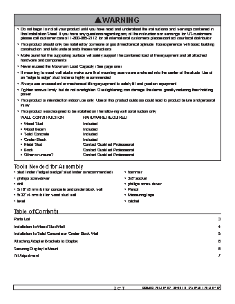
Tools Needed for Assembly
• stud finder ("edge to edge" stud finder is recommended) • hammer
• phillips screwdriver • 3/8” socket
• drill • phillips screw driver
• 5/16" (8 mm) bit for concrete and cinder block wall • Pencil
• 5/32" (4 mm) bit for wood stud wall • Measuring tape
• level • ratchet
Table of Contents
Parts List.................................................................................................................................................................................3
Installation to Wood Stud Wall ................................................................................................................................................4
Installation to Solid Concrete or Cinder Block Wall ................................................................................................................5
Attaching Adapter Brackets to Display ...................................................................................................................................6
Securing Display to Mount......................................................................................................................................................6
Tilt Adjustment ........................................................................................................................................................................7
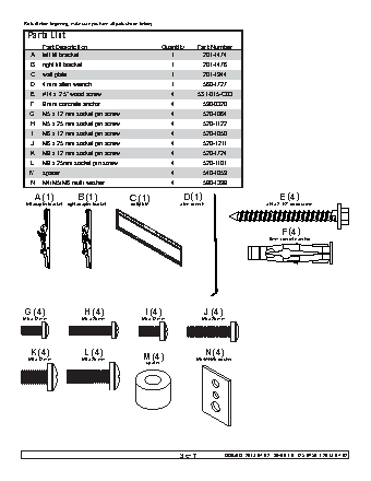
2 of 7 ISSUED: 2013-07-02 SHEET #: 125-9459-1 2013-07-02Parts (Before beginning, make sure you have all parts shown below). Parts List Part Description Quantity Part Number A left tilt bracket 1 201-1474 B right tilt bracket 1 201-1476 C wall plate 1 201-1944 D 4 mm allen wrench 1 560-1727 E #14 x 2.5" wood screw 4 5S1-015-C03 F 8 mm concrete anchor 4 590-0320 G M5 x 12 mm socket pin screw 4 520-1064 H M5 x 25 mm socket pin screw 4 520-1122 I M6 x 12 mm socket pin screw 4 520-1050 J M6 x 25 mm socket pin screw 4 520-1211 K M8 x 12 mm socket pin screw 4 520-1724 L M8 x 25mm socket pin screw 4 520-1101 M spacer 4 540-1059 N M4/M5/M6 multi washer 4 580-1398 A (1) B (1) C (1) D (1) E (4) left adapter bracket right adapter bracket wall plate allen wrench #14 x 2-1/2" wood screw F (4) 8mm concrete anchor G (4) H (4) I (4) J (4) M5 x 12 mm M5 x 25 mm M6 x 12 mm M6 x 25 mm K (4) L (4) N (4) M8 x 12 mm M8 x 25 mm M (4) M5/M4/M6 washer spacer 3 of 7 ISSUED: 2013-07-02 SHEET #: 125-9459-1 2013-07-02