На сайте 123327 инструкций общим размером 499.11 Гб , которые состоят из 6232366 страниц
Фото

Руководство пользователя NEC PD01CMB. Основные функции, характеристики и условия эксплуатации изложены на 8 страницах документа в pdf формате.
Доступно к просмотру 8 страниц. Рекомендуем вам скачать файл инструкции, поскольку онлайн просмотр документа может сильно отличаться от оригинала.
I N S T A L L A T I O N                             I N S T R U C T I O N S
I N S T R U C T I O N S                          D ' I N S T A L L A T I O N
M O N T A G E A N L E I T U N G
Extension Columns with Cable Cover
Colonnes d'extension avec protege-cable
Ausziehsaulen mit Kabelabdeckung
CPAE Columns
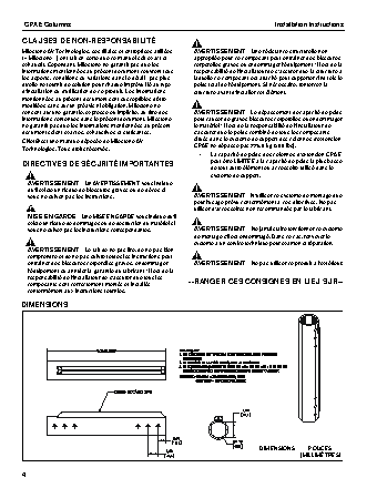
CPAE Columns                                                                     Installation Instructions
DISCLAIMER
Milestone AV Technologies and its affiliated corporations and  WARNING: Failure to provide adequate structural strength
subsidiaries (collectively "Milestone"), intend to make this  for this component can result in serious personal injury or
manual accurate and complete. However, Milestone makes no  damage to equipment!  It is the installer’s responsibility to
claim that the information contained herein covers all details,  make sure the structure to which this component is attached
conditions or variations, nor does it provide for every possible  can support five times the combined weight of all equipment.
contingency in connection with the installation or use of this  Reinforce the structure as required before installing the
product. The information contained in this document is subject  component.
to change without notice or obligation of any kind. Milestone
makes no representation of warranty, expressed or implied,
regarding the information contained herein. Milestone assumes  WARNING: Exceeding the weight capacity can result in
no responsibility for accuracy, completeness or sufficiency of  serious personal injury or damage to equipment!  It is the
the information contained in this document.             installer’s responsibility to make sure the combined weight of
all components located within the mounting system of the
Chief® is a registered trademark of Milestone AV Technologies.  CPAE Extension Columns does not exceed 500 lbs (226.8 kg).
All rights reserved.
•  The weight capacity of the CPAE Extension Columns
may be LIMITED to the lowest weight capacity of any
other component or accessory used within the
IMPORTANT SAFETY INSTRUCTIONS                         mounting system.
WARNING: A WARNING alerts you to the possibility of   WARNING: Use this mounting system only for its intended
serious injury or death if you do not follow the instructions.  use as described in these instructions. Do not use
attachments not recommended by the manufacturer.
CAUTION: A CAUTION alerts you to the possibility of
damage or destruction of equipment if you do not follow the  WARNING: Never operate this mounting system if it is
corresponding instructions.                           damaged. Return the mounting system to a service center for
examination and repair.
WARNING: Failure to read, thoroughly understand, and
follow all instructions can result in serious personal injury,  WARNING: Do not use this product outdoors.
damage to equipment, or voiding of factory warranty!  It is the
installer’s responsibility to make sure all components are
properly assembled and installed using the instructions
provided.                                                  --SAVE THESE INSTRUCTIONS--
DIMENSIONS
NOTES:
1. CPAE STYLE COLUMNS ARE AVAILABLE IN A VARIETY OF LENGTHS
2. THE PART NUMBER WILL DESIGNATE THE LENGTH
3. STANDARD COLOR IS BLACK. AN 'S' OR 'W' AT THE END OF
THE PART NUMBER SIGNIFIES SILVER OR WHITE, RESPECTIVELY
EXAMPLES: CPAE030 = 30CM LONG, BLACK
CPAE150W = 150CM LONG, WHITE
TRACK
1.50
38.1
0.75
19.1                  1.90
48.3
DIMENSIONS:       INCHES
[MILLIMETERS]
2
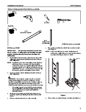
Installation Instructions                                                                CPAE Columns
TOOLS REQUIRED FOR INSTALLATION
1/2"                  1/2"
nut driver
PARTS
A (1)
[Extension column]
B (1)
[cable cover]
(2-CPAE300)
(CPAE-024 shown as example)
INSTALLATION                                          5.  Place cable cover (B) onto column (A) at desired location.
(See Figure 1)
IMPORTANT ! : The following procedure assumes that    NOTE: Cable cover (B) may be cut into smaller pieces if
the UL Listed CPA ceiling plate (not included) has been      desired. Use a utility knife to cut cover and place pieces
properly installed following instructions provided with      at desired mounting locations on column.
ceiling plate.
1.  Install CPAE Series Extension column into UL Listed CPA
ceiling plate (not included) following instructions included
with ceiling plate.
6
NOTE: Installation of hex head self-tapping screws (included
with Listed Chief accessories and mounts) will be
easier when screws are carefully aligned with holes in
extension column, and a drill and nut driver is used. If a
drill will NOT be used, a small amount of pressure will    5
be needed to get the self-tapping screws started.
2.  Secure extension column following instructions included
with ceiling plate.
5
WARNING: Exceeding the weight capacity can result in                                      6
serious personal injury or damage to equipment!  It is the
installer’s responsibility to make sure the combined weight of
all components located within the mounting system of the
CPAE Extension Columns does not exceed 500 lbs (226.8 kg).
•   The weight capacity of the CPAE Extension Columns
may be LIMITED to the lowest weight capacity of any
other component or accessory used within the
mounting system.
3.  Install and secure mount (not included) to lower end of
extension column (A) following instructions included with               Figure 1
mount.
4.  Remove adhesive from back of cable cover (B).     6.  Route cables as desired through cover (B). (See Figure 1)
3