На сайте 123396 инструкций общим размером 499.32 Гб , которые состоят из 6234837 страниц
Фото
Руководство пользователя NEC NP30ZL. Основные функции, характеристики и условия эксплуатации изложены на 4 страницах документа в pdf формате.
Доступно к просмотру 4 страницы. Рекомендуем вам скачать файл инструкции, поскольку онлайн просмотр документа может сильно отличаться от оригинала.
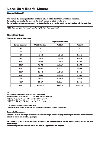
Lens Unit User’s Manual
Model NP30ZL
This manual discusses specifications and focus adjustment for the NP30ZL short focus zoom lens.
For cautions on handling the lens, see the User’s Manual supplied with the lens.
For instructions on mounting, removing, and cleaning the lens, see the User’s Manual supplied with the projector.
NOTE: The drawings in this manual may differ slightly from the actual product.
Specifications
Throw distance (Unit: m)
Projector model name
Screen size (inch)      PA600X/PA500X              PA550W                 PA500U
30”                      -                      -                       -
40”                      -                      -                       -
60”                   1.0-1.3                1.0-1.3                 1.0-1.3
80”                   1.3-1.7                1.4-1.8                 1.4-1.8
100”                  1.6-2.1                1.7-2.2                 1.7-2.2
120”                  2.0-2.6                2.1-2.7                 2.0-2.7
150”                  2.5-3.2                2.6-3.4                 2.6-3.4
200”                  3.3-4.3                3.5-4.5                 3.4-4.5
240”                  4.0-5.2                4.2-5.5                 4.1-5.4
300”                  5.0-6.5                5.3-6.8                 5.2-6.8
400”                  6.7-8.7                7.0-9.1                 6.9-9.0
500”                 8.4-10.9                8.8-11.4               8.7-11.3
TIP:
Calculation of the throw distance from the screen size (m)
PA600X/PA500X: H x 0.8 to H x 1.1 : 1.0 m (min.) to 10.9 m (max.)
PA550W: H x 0.8 to H x 1.0 : 1.0 m (min.) to 11.4 m (max.)
PA500U: H x 0.8 to H x 1.0 : 1.0 m (min.) to 11.3 m (max.)
* “H” (Horizontal) refers to the screen width.
* Figures differ by several % with the table above because the calculation is approximate.
Lens shifting range
The lens shift dials on the projector allow you to move the position of the projected image in the vertical and horizontal
directions based on the following ranges.
Description of symbols: V indicates vertical (height of the projected image), H indicates horizontal (width of the pro-
jected image).
For adjusting the lens shift, see the User’s Manual supplied with the projector.
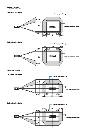
PA600X/PA500X
Desk/front projection
Width of projected image
0.35V
1V
Height of projected image
0.1V        0.1H        0.1H
0.2H       1H        0.2H
Ceiling/front projector
Width of projected image
0.2H       1H        0.2H
0.1V        0.1H        0.1H
1V                              Height of projected image
0.35V
PA550W/PA500U
Desk/front projection
Width of projected image
0.5V
1V
Height of projected image
0.1V        0.1H       0.1H
0.2H       1H        0.2H
Ceiling/front projector
Width of projected image
0.2H       1H        0.2H
0.1V        0.1H       0.1H
1V                                Height of projected image
0.5V
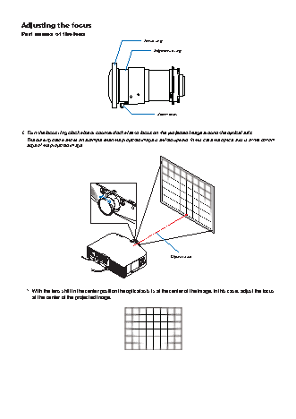
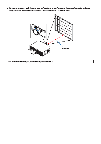
Adjusting the focus
Part names of the lens
Focus ring
Edge focus ring
Zoom lever
1.  Turn the focus ring clockwise or counterclockwise to focus on the projected image around the optical axis.
The drawing below shows an example when the projected image is shifted upward. In this case the optical axis is at the bottom
edge of the projected image.
Optical axis
*  With the lens shift in the center position the optical axis is at the center of the image. In this case, adjust the focus
at the center of the projected image.