На сайте 126950 инструкций общим размером 514.06 Гб , которые состоят из 6425133 страниц
Фото
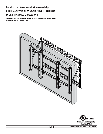
Руководство пользователя NEC Videowall Mount PD02VW MFS 46 55 L. Основные функции, характеристики и условия эксплуатации изложены на 12 страницах документа в pdf формате.
Доступно к просмотру 12 страниц. Рекомендуем вам скачать файл инструкции, поскольку онлайн просмотр документа может сильно отличаться от оригинала.
Installation and Assembly:
Full Service Video Wall Mount
Model: PD02VW MFS 46 55 L
Designed for NEC MultiSync® 46" and 55" XUN/V, XS and P Series
Manufactured by Peerless-AV
Max UL Load Capacity:
125 lb (57 kg)
1 of 12                   ISSUED: 02-21-13   SHEET #: 145-9017-1
NOTE: Read entire instruction sheet before you start installation and assembly.
WARNING
•  Do not begin to install your product until you have read and understood the instructions and warnings contained in
this Installation Sheet. If you have any questions regarding any of the instructions or warnings, for US customers
please call customer care at 1-800-865-2112, for all international customers, please contact your local distributor.
•  This product should only be installed by someone of good mechanical aptitude, has experience with basic building
construction, and fully understands these instructions.
•  Make sure that the supporting surface will safely support the combined load of the equipment and all attached
hardware and components.
•  Never exceed the Maximum UL Load Capacity. See page one.
•  If mounting to wood wall studs, make sure that mounting screws are anchored into the center of the studs. Use of
an "edge to edge" stud ? nder is highly recommended.
•  Always use an assistant or mechanical lifting equipment to safely lift and position equipment.
• Tighten screws ? rmly, but do not overtighten. Overtightening can damage the items, greatly reducing their holding
power.
•  This product is intended for indoor use only. Use of this product outdoors could lead to product failure and personal
injury.
•  This product was designed to be installed on the following wall construction only;
WALL CONSTRUCTION               HARDWARE REQUIRED
•  Wood Stud                     Included
•  Wood Beam                    Included
•  Solid Concrete               Included
•  Cinder Block                 Included
•  Metal Stud                   Contact Quali? ed Professional (not evaluated by UL)
•  Brick                        Contact Quali? ed Professional (not evaluated by UL)
•  Other or unsure?             Contact Quali? ed Professional (not evaluated by UL)
Tools Needed for Assembly                                Accessories
• stud ? nder ("edge to edge" stud ? nder  is recommended)  •  RK02 MFS Cable Release Kit
•  phillips screwdriver                                  •  CK02## Wall Plate Connector Kits
• drill
•  5/16" (8 mm) bit for concrete and cinder block wall
•  5/32" (4 mm) bit for wood stud wall
•  level
Table of Contents
Horizontal and Vertical Video Wall Mount Assembly Formula ................................................................................................3
Parts List.................................................................................................................................................................................4
Installation to Wood Stud Wall ................................................................................................................................................5
Installation to Solid Concrete or Cinder Block ........................................................................................................................6
Installing Tilt Brackets .............................................................................................................................................................7
Display Adjustment ...................................................................................................................................................... 8 and 9
Mounting and Removing Flat Panel Display.............................................................................................................10 and 11
2 of 12                   ISSUED: 02-21-13   SHEET #: 145-9017-1
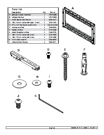
A Parts List Description Qty. Part # A pull?out mount assembly 1 145?T1665 B adapter bracket 2 145?T1669 C mesh sleeve (not shown) 1 600?1014 D M5 x 10 mm socket pin type?F screw 2 520?1164 E #14 x 2.5" hex head wood screw 4 5S1?015?C03 F concrete anchor 4 590?0320 G fender washer 4 540?1008 H nylon shoulder washer 4 590?2233 I M6 x 12 mm socket pin screw 4 520?1050 J M8 x 15 mm socket pin screw 4 520?1068 K 4 mm allen wrench 1 560?9646 L cable tie (not shown) 2 560?9711 B D E F G H I J K 3 of 12 ISSUED: 02-21-13 SHEET #: 145-9017-1