На сайте 123379 инструкций общим размером 499.27 Гб , которые состоят из 6234097 страниц
Фото
Руководство пользователя SHOP VAC Micro 4. Основные функции, характеристики и условия эксплуатации изложены на 9 страницах документа в pdf формате.
Доступно к просмотру 9 страниц. Рекомендуем вам скачать файл инструкции, поскольку онлайн просмотр документа может сильно отличаться от оригинала.
127(  7KLV LV D JHQHULF PDQXDO  ,WHPV VKRZQ PD\ QRW DSSO\ WR \RXU YDFXXP
3OHDVH FRQWDFW FXVWRPHU VHUYLFH ZLWK TXHVWLRQV
ATTENTION!
Read all safety  rules careful-
ly before attempting to oper-
ate. Retain for future reference.
DANGER!
Never operate this unit when
flammable materials or vapors
are present because electrical
devices produce arcs or sparks
that can cause a fire or explo-
sion.
NEVER  OPERATE
UNATTENDED!
WARNING!
Do NOT use this vacuum cleaner
to vacuum lead paint debris
because this may disperse fine
lead particles into the air.  This
vacuum cleaner is not intended
for use under EPA Regulation
40 CFR Part 745 for lead paint
material cleanup.
SHOP-VAC CORPORATION                   Patents Issued and Pending. Printed in U.S.A.
2323 Reach Road, P.O. Box 3307
Williamsport, PA 17701-0307            © 2010 Shop-Vac Corporation. All rights reserved.
(570) 326-3557
Web site: www.shopvac.com
SHOP-VAC CANADA
1770 Appleby Line
Burlington, Ontario L7L 5P8
(905) 335-9730
Web site: www.shopvac.ca
Shop Vac-Mexico, S.A. de C.V.
Calle Ninos Heros #1553
Colonia Agua Blanca
45235 - Zapopan, Jalisco
52 (33) 3188 6388
MSC1896
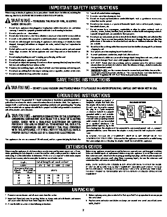
IMPORTANT SAFETY INSTRUCTIONS
When using an electrical appliance, basic precautions should always be followed, including the   13.  Turn off all controls before unplugging.
following: READ ALL INSTRUCTIONS BEFORE USING THIS APPLIANCE.  14.  Use extra care when cleaning on stairs.
15.  Do not use to pick up flammable or combustible liquids such as gasoline or use in areas
WARNING – TO REDUCE THE RISK OF FIRE, ELECTRIC            where they may be present.
SHOCK OR INJURY:                                       16.  Do not use your cleaner as a sprayer of flammable liquids such as oil base paints, lacquers,
household cleaners, etc.
1.   Do not leave appliance when plugged in. Unplug from outlet when not in use and before   17.  Do not vacuum toxic, carcinogenic, combustible or other hazardous materials such as
servicing. Connect to a properly grounded outlet only. See Grounding Instructions.
asbestos, arsenic, barium, beryllium, lead, pesticides or other health endangering materials.
2.   Do not expose to rain – store indoors.                   Specially designed units are available for these purposes.
3.   Do not allow to be used as a toy. Close attention is necessary when used by or near children.  18.  Do not pick up soot, cement, plaster or drywall dust without cartridge filter and collection filter
4.   Use only as described in this manual. Use only Manufacturer’s recommended attachments.  bag in place. These are very fine particles that may pass through the foam and affect the
5.   Do not use with damaged cord or plug. If appliance is not working as it should, has been   performance of the motor or be exhausted back into the air. Additional collection filter bags
dropped, damaged, left outdoors or dropped into water, contact Shop-Vac Corporation for   are available.
assistance.                                             19.  Do not leave the cord lying on the floor once you have finished the cleaning job. It can become
6.   Do Not: pull or carry by cord, use cord as a handle, close a door on cord or pull cord around   a tripping hazard.
sharp edges or corners. Do not run appliance over cord. Keep cord away from heated sur-  20.  Use special care when emptying heavily loaded tanks.
faces.                                                  21.  To avoid spontaneous combustion, empty tank after each use.
7.   Do not unplug by pulling on cord. To unplug, grasp the plug; not the cord.  22.  The operation of a utility vac can result in foreign objects being blown into eyes, which can
8.   Do not handle plug or appliance with wet hands.          result in eye damage. Always wear safety goggles when operating vacuum.
9.   Do not put any object into openings. Do not use with any openings blocked; keep free of dust,   23.  STAY ALERT. Watch what you are doing and use common sense. Do not use vacuum
lint, hair and anything that may reduce air flow.           cleaner when you are tired, distracted or under the influence of drugs, alcohol or medication
10.  Keep hair, loose clothing, fingers and all parts of body away from openings and moving parts.  causing diminished control.
11.  Do not pick up anything that is burning or smoking, such as cigarettes, matches or hot ashes.  24.  WARNING! Do NOT use this vacuum cleaner to vacuum lead paint debris because this
may disperse fine lead particles into the air.  This vacuum cleaner is not intended for use
12.  Do not use without dust bag and/or filters in place.
under EPA Regulation 40 CFR Part 745 for lead paint material cleanup.
SAVE THESE INSTRUCTIONS
WARNING – DO NOT LEAVE VACUUM UNATTENDED WHEN IT IS PLUGGED IN AND/OR OPERATING. UNPLUG UNIT WHEN NOT IN USE.
GROUNDING INSTRUCTIONS
This appliance must be grounded. If it should malfunction or breakdown, grounding provides a   the plug illustrated in sketch A. A
path of least resistance for electric current to reduce the risk of electric shock. This appliance is   temporary adapter that looks like
equipped with a cord having an equipment-grounding conductor and grounding plug. The plug   the adapter illustrated in sketches
must be inserted into an appropriate outlet that is properly installed and grounded in accordance   B and C may be used to connect
with all local codes and ordinances.                       this plug to a 2-pole receptacle
as shown in sketch B if a properly
grounded outlet is not available.
WARNING – IMPROPER CONNECTION OF THE EQUIPMENT-       The temporary adapter should be
GROUNDING CONDUCTOR CAN RESULT IN A RISK OF ELECTRIC   used only until a properly grounded
SHOCK. CHECK WITH A QUALIFIED ELECTRICIAN OR SERVICE   outlet (sketch A) can be installed
by a qualified electrician.  The
PERSON IF YOU ARE IN DOUBT AS TO WHETHER THE OUTLET IS   green colored rigid ear, lug or the
PROPERLY GROUNDED. DO NOT MODIFY THE PLUG PROVIDED    like extending from the adapter must be connected to a permanent ground such as a properly
WITH THE APPLIANCE – IF IT WILL NOT FIT THE OUTLET, HAVE A   grounded outlet box cover. Whenever the adapter is used, it must be held in place by a metal
PROPER OUTLET INSTALLED BY A QUALIFIED ELECTRICIAN.   screw.
IN CANADA,  THE USE OF A  TEMPORARY ADAPTER IS NOT PERMITTED BY  THE
CANADIAN ELECTRICAL CODE.  Make sure that the appliance is connected to an outlet having
This appliance is for use on a nominal 120-volt circuit, and has a grounded plug that looks like
the same configuration as the plug. No adapter should be used with this appliance.
EXTENSION CORDS
When using the appliance at a distance where an extension cord becomes necessary, a 3-con-  Before using appliance, inspect power cord for loose or exposed wires and damaged insulation.
ductor grounding cord of adequate size must be used for safety, and to prevent loss of power and   Make any needed repairs or replacements before using your appliance. Use only three-wire out-
overheating. Use the table below to determine A.W.G. wire size required. To determine ampere   door extension cords which have three-prong grounding-type plugs and three-pole receptacles
rating of your vacuum, refer to nameplate located on rear of motor cover.   which accept the extension cord’s plug. When vacuuming liquids, be sure the extension cord
connection does not come in contact with the liquid.
Volts       Total length of cord in feet
120V         25     50    100    150            NOTE:  STATIC SHOCKS ARE COMMON IN DRY AREAS OR WHEN THE RELATIVE HUMID-
ITY OF THE AIR IS LOW. THIS IS ONLY TEMPORARY AND DOES NOT AFFECT THE USE
Ampere Rating                                       OF THE APPLIANCE. TO REDUCE THE FREQUENCY OF STATIC SHOCKS IN YOUR HOME,
More    Not More          AWG                       THE BEST  REMEDY IS TO ADD MOISTURE TO THE AIR WITH A CONSOLE OR INSTALLED
Than        Than                                    HUMIDIFIER.
0   -  6       18     16    16     14
6   -  10     18     16    14     12
10 -  12       16     16    14     12
12 -  16       14     12  Not recommended
UNPACKING
1.   Remove vacuum cleaner and all accessories from the carton.  4.   Before replacing cover, please refer to Dry Pick up or Wet Pick up operation to ensure proper
filter installation.
2.   Important: Open tank cover by pushing latches or clamps outward with thumbs and remove
any accessories that may have been shipped in the tank.  5.   Replace cover and make sure latches or clamps are secured over raised area of tank cover.
3.   Assemble dolly or caster system following instructions.     I=ON, O=OFF
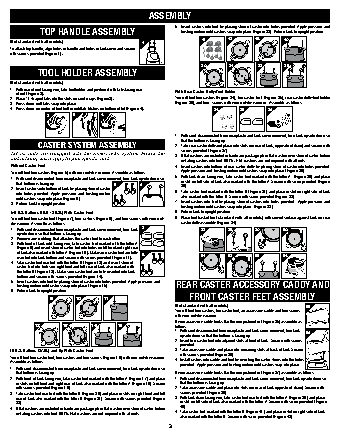
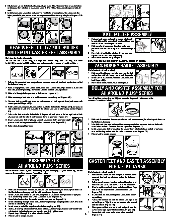
ASSEMBLY
5.   Insert casters into feet by placing stem of caster into holes provided. Apply pressure and
TOP HANDLE ASSEMBLY                                twisting motion until casters snap into place (Figure 23). Return tank to upright position.
16       17        18        19
(Not standard with all models)                 1                                     A         A
A
To attach top handle, align holes in handle and holes in tank cover and secure                          B
with screws provided (Figure 1).                                                            A
A         A
20       21         22       23
B     A
B
TOOL HOLDER ASSEMBLY
B  B
(Not standard with all models)
A    B
B
1.  With rear of unit facing you, take tool holder and position it with tabs facing rear   With Rear Caster Dolly/Tool Holder
of unit (Figure 2).
2.  Place “J” shaped tabs into the slots on cord wraps (Figure3).  You will find four casters (Figure 24), two caster feet  (Figure 25), rear caster dolly/tool holder
3.  Press down until tabs snap into place.                 (Figure 26), and four  screws with your wet/dry vacuum.  Assemble as follows:
4.   Press down on center of tool holder until tab latches on bottom of lid (Figure 4).  24  25  26
2        3         4
1.   With cord disconnected from receptacle and tank cover removed, turn tank upside down so
that the bottom is facing up.
CASTER SYSTEM ASSEMBLY                           2.   Take rear caster dolly and place into slots (on rear of tank, opposite of drain) and secure with
screws provided (Figure 27).
1RW  DOO  XQLWV  DUH  HTXLSSHG  ZLWK  WKH  VDPH  FDVWHU  V\VWHP   )ROORZ  WKH   3.   If flat washers are included in hardware package place flat washer over stem of caster before
LQVWUXFWLRQV  ZKLFK DSSO\ WR \RXU VSHFLILF XQLW
installing casters into feet. NOTE : Flat washers are not required with all units.
Without Caster Feet                                        4.   Insert casters into bottom of rear caster dolly by placing stem of caster into holes provided.
You will find four casters (Figure 5) with your wet/dry vacuum. Assemble as follows:  Apply pressure and twisting motion until casters snap into place (Figure 28).
5.   With tank drain facing you, take caster foot marked with the letter A  (Figure 29) and place
1.   With cord disconnected from receptacle and tank cover removed, turn tank upside down so
that bottom is facing up.                                  in slot on left side of tank also marked with the letter A. Secure with screw provided (Figure
5         6             30).
2.   Insert casters into bottom of tank by placing stem of caster
into holes provided. Apply pressure and twisting motion   6.   Take caster foot marked with the letter B (Figure 31) and place in slot on right side of tank
until casters snap into place (Figure 6).                  also marked with the letter B. Secure with screw provided (Figure 32).
3.   Return tank to upright position.                      7.   Insert casters into feet by placing stem of casters into holes provided.  Apply pressure and
twisting motion until casters snap into place  (Figure 33).
5-8 U.S. Gallons (18.9 - 30.2L) With Caster Feet           8.   Return tank to upright position.
You will find four caster feet (Figure 7), four casters (Figure 8), and four screws with your wet/  9.   Place tool basket (not standard with all models) with curved surface against tank on rear
dry vacuum. Assemble as follows:                             caster dolly assembly (Figure 34).
1.   With cord disconnected from receptacle and tank cover removed, turn tank   7  27  28  29     30
upside down so that bottom is facing up.
2.   Remove any webbing that attaches the caster feet to each other.
3.    With front of tank inlet facing you, take caster feet marked with the letter A
(Figure 9) and insert stem of caster foot into holes on left front and right rear       A         A    B
of tank also marked with letter A (Figure 10). Make sure caster feet are fully   8
inserted into tank bottom and secure with screws provided (Figure 11).  31  32        33        34
4.   Take caster feet marked with the letter B (Figure 12) and insert stem of
caster foot into holes on right front and left rear of tank also marked with
A
the letter B (Figure 13). Make sure caster feet are fully inserted into tank   B
bottom and secure with screws provided (Figure 14).                            A   B
5.   Insert casters into feet by placing stem of caster into holes provided. Apply pressure and
twisting motion until casters snap into place (Figure 15).  REAR CASTER ACCESSORY CADDY AND
6.  Return tank to upright position.
9      A   10   A   11                            FRONT CASTER FEET ASSEMBLY
(Not standard with all models)                 35
A
You will find four casters, two caster feet, an accessory caddy and four screws
A
with your wet/dry vacuum.
A         A
If your accessory caddy looks like the one pictured in (Figure 35) assemble as
12        13        14       15                   follows.
B         B     A
1.  With cord disconnected from receptacle and tank cover removed, turn tank   36
B  B                                   upside down so that the bottom is facing up.
2.  Insert two caster feet into adjacent slots at front of tank.  Secure with screws
provided.
A
B          B
10 U.S. Gallons (37.8L) and Up With Caster Feet            3.  Take accessory caddy and place into remaining slots at back of tank. Secure
with screws provided (Figure 36).
You will find four caster feet, four casters and four screws (Figure 16) with your wet/dry vacuum.   4.  Install casters into caddy and feet by inserting the caster stems into the holes
Assemble as follows:
provided.  Apply pressure and twisting motion until casters snap into place.
1.   With cord disconnected from receptacle and tank cover removed, turn tank upside down so
that bottom is facing up.                                If your accessory caddy looks like the one pictured in (Figure 37) assembly as follows.
2.   With front of tank facing you, take caster feet marked with the letter A (Figure 17) and place   1.  With cord disconnected from receptacle and tank cover removed, turn tank upside down so
in slots on left front and right rear of tank also marked with the letter A (Figure 18). Secure   that the bottom is facing up.
with screws provided (Figure 19).                        2.  Take accessory caddy and place into slots (on rear of tank opposite of drain). Secure with
3.   Take caster feet marked with the letter B (Figure 20) and place in slots on right front and left   screws provided (Figure 38).
rear of tank also marked with the letter B (Figure 21). Secure with screws provided (Figure   3.  With tank drain facing you, take caster foot marked with the letter A (Figure 39) and place
22).                                                       in slot on left side of tank also marked with the letter A. Secure with screw provided (Figure
4.   If flat washers are included in hardware package place flat washer over stem of caster before   40).
installing casters into feet. NOTE: Flat washers are not required with all units.  4.  Take caster foot marked with the letter B (Figure 41) and place in slot on right side of tank
also marked with the letter B. Secure with screw provided (Figure 42).