На сайте 127126 инструкций общим размером 514.8 Гб , которые состоят из 6432831 страницы
Фото
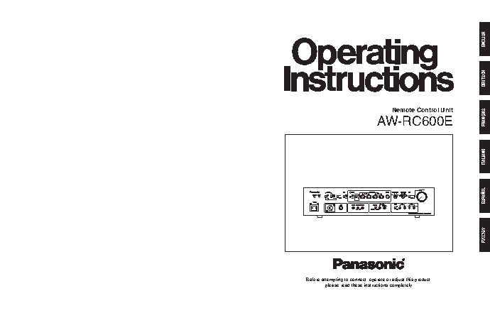
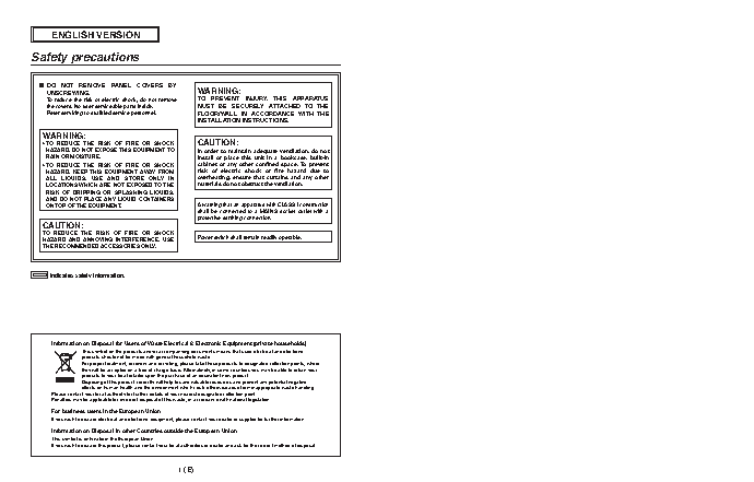
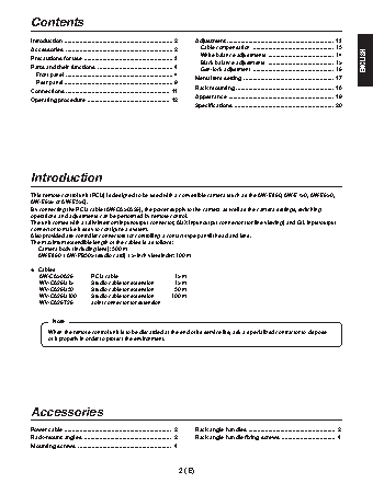
Руководство пользователя PANASONIC AW-RC600. Основные функции, характеристики и условия эксплуатации изложены на 124 страницах документа в pdf формате.
Доступно к просмотру 123 страницы. Рекомендуем вам скачать файл инструкции, поскольку онлайн просмотр документа может сильно отличаться от оригинала.
ENGLISH
DEUTSCH
Remote Control Unit
AW-RC600E                                              FRANCAIS
ITALIANO
ESPANOL
РУССКИЙ
Matsushita Electric Industrial Co., Ltd.
Web Site: http://www.panasonic.co.jp/global/
Printed in Japan
Gedruckt in Japan
Imprime au Japon                                                                                                                                 Before attempting to connect, operate or adjust this product,
Stampato in Giappone                                                                                                                                       please read these instructions completely.
Impreso en Japon
Напечатано в Япони                                                                      F0306S0  D E
VQTB0117
ENGLISH VERSION
Safety precautions
?  DO  NOT  REMOVE  PANEL  COVERS  BY
UNSCREWING.                                       WARNING:
To reduce the risk of electric shock, do not remove    TO  PREVENT  INJURY,  THIS  APPARATUS
the covers. No user serviceable parts inside.     MUST  BE  SECURELY  ATTACHED  TO  THE
Refer servicing to qualified service personnel.   FLOOR/WALL  IN  ACCORDANCE  WITH  THE
INSTALLATION INSTRUCTIONS.
WARNING:
•  TO  REDUCE  THE  RISK  OF  FIRE  OR  SHOCK      CAUTION:
HAZARD, DO NOT EXPOSE THIS EQUIPMENT TO           In order to maintain adequate ventilation, do not
RAIN OR MOISTURE.                                 install  or  place  this  unit  in  a  bookcase,  built-in
•  TO  REDUCE  THE  RISK  OF  FIRE  OR  SHOCK      cabinet  or  any  other  confined  space. To  prevent
HAZARD, KEEP THIS  EQUIPMENT AWAY FROM            risk  of  electric  shock  or  fire  hazard  due  to
ALL  LIQUIDS.  USE  AND  STORE  ONLY  IN          overheating,  ensure  that  curtains  and  any  other
LOCATIONS WHICH ARE NOT EXPOSED TO THE            materials do not obstruct the ventilation.
RISK  OF  DRIPPING  OR  SPLASHING  LIQUIDS,
AND DO NOT PLACE ANY LIQUID CONTAINERS
ON TOP OF THE EQUIPMENT.                          A warning that an apparatus with CLASS I construction
shall be connected to a MAINS socket outlet with a
protective earthing connection.
CAUTION:
TO  REDUCE  THE  RISK  OF  FIRE  OR  SHOCK
HAZARD  AND  ANNOYING  INTERFERENCE,  USE          Power switch shall remain readily operable.
THE RECOMMENDED ACCESSORIES ONLY.
indicates safety information.
Information on Disposal for Users of Waste Electrical & Electronic Equipment (private households)
This symbol on the products and/or accompanying documents means that used electrical and electronic
products should not be mixed with general household waste.
For proper treatment, recovery and recycling, please take these products to designated collection points, where
they will be accepted on a free of charge basis. Alternatively, in some countries you may be able to return your
products to your local retailer upon the purchase of an equivalent new product.
Disposing of this product correctly will help to save valuable resources and prevent any potential negative
effects on human health and the environment which could otherwise arise from inappropriate waste handling.
Please contact your local authority for further details of your nearest designated collection point.
Penalties may be applicable for incorrect disposal of this waste, in accordance with national legislation.
For business users in the European Union
If you wish to discard electrical and electronic equipment, please contact your dealer or supplier for further information.
Information on Disposal in other Countries outside the European Union
This symbol is only valid in the European Union.
If you wish to discard this product, please contact your local authorities or dealer and ask for the correct method of disposal.
1 (E)
Contents
Introduction  ....................................................................... 2  Adjustment  ...................................................................... 13
Accessories  ...................................................................... 2    Cable compensation  ..................................................... 13
White balance adjustments  ........................................... 14
Precautions for use  .......................................................... 3
Black balance adjustments  ........................................... 15  ENGLISH
Parts and their functions  ................................................. 4    Gen-lock adjustment  ..................................................... 16
Front panel  ...................................................................... 4  Menu item setting  ........................................................... 17
Rear panel  ....................................................................... 9
Rack mounting  ................................................................ 18
Connections  .................................................................... 11
Appearance  ..................................................................... 19
Operating procedure  ...................................................... 12
Specifications  ................................................................. 20
Introduction
This remote control unit (RCU) is designed to be used with a convertible camera (such as the AW-E860, AW-E750, AW-E650,
AW-E655 or AW-E350).
By connecting the RCU cable (AW-CA50A26), the power supply to the camera as well as the camera settings, switching
operations and adjustments can be performed by remote control.
The unit comes with a tally/intercom input/output connector, AUX input/output connector (for line viewing) and G/L input/output
connector to make it easy to configure a system.
Also provided are controller connectors for controlling a contact-type pan/tilt head and lens.
The maximum extendible length of the cables is as follows:
Camera body (including lens): 300 m
AW-E860 + AW-PB305 (studio card) + 5-inch viewfinder: 100 m
?   Cables
AW-CA50A26       RCU cable                  15 m
WV-CA26U15       Studio cable for extension   15 m
WV-CA26U30       Studio cable for extension   30 m
WV-CA26U100      Studio cable for extension   100 m
WV-CA26T26       Joint connector for extension
Note
When the remote control unit is to be discarded at the end of its service life, ask a specialized contractor to dispose
of it properly in order to protect the environment.
Accessories
Power cable  ......................................................................  2   Rack angle handles  .........................................................  2
Rack-mount angles  .........................................................  2   Rack angle handle fixing screws  ...................................  4
Mounting screws  .............................................................  4
2 (E)