На сайте 123373 инструкции общим размером 499.26 Гб , которые состоят из 6233729 страниц
Фото

Руководство пользователя B&W M-1. Основные функции, характеристики и условия эксплуатации изложены на 6 страницах документа в pdf формате.
Доступно к просмотру 5 страниц. Рекомендуем вам скачать файл инструкции, поскольку онлайн просмотр документа может сильно отличаться от оригинала.
ENGLISH
Welcome to Bowers & Wilkins and M-1
Thank you for choosing Bowers & Wilkins. When John Bowers                                                    ENGLISH
first established our company he did so in the belief that
imaginative design, innovative engineering and advanced
technology were keys that could unlock the enjoyment of audio
in the home. His belief is one that we continue to share and it
inspires every product we design.
Contents
ENGLISH	  2
Welcome to Bowers & Wilkins and M-1  2
1 Contents  3
2 Positioning     3
2.1  2- and 2.1-channel (stereo)   3
2.2  Multi-channel home theatre   3
2.2.1     5.1-channel    3
2.2.2     6.1-channel    3
2.2.3     7.1-channel    3
3 Moving the ball socket position   4
3.1  Removing the table stand base   4
3.2  Removing and turning the back cover   4
3.3  Rotating the stem  4
4 Connecting using the table stand   5
5 Fitting and connecting using the
wall bracket 5
6 Adjusting the angle of the speaker   6
7 Rotating the badge  6
8 Environmental Information
6
www.bowers-wilkins.com
2
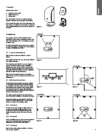
1 Contents
Check that you have:                                                                                         ENGLISH
1.  Speaker on table stand
2.  Wall bracket cover
3.  Wall bracket
The wall bracket and cover are supplied clipped
together. Pull them apart if required for installation.
If you peel off the rubber mat on the underside of the
table stand, you will find a Torx key that you will need
when making adjustments to the way the speaker is   Figure 1
mounted.
2 Positioning                       2-channel
The speakers may be used in distributed audio
applications, where they are typically mounted more
than 2.5m (8 ft) high on the wall pointing down. (see
Sections 3 & 5)
For other applications, choose where you are going
to place the speakers, using figures 2-6 according to
the type of installation you want.
2.1  2- and 2.1-channel (stereo)
Figure 2 shows a range of angles to a central
listener.
If the angle is less than 40?, you will not get sufficient   Figure 2
left to right separation.
If the angle is greater than 60?, you may begin to
detect a ‘hole in the middle’ effect, especially if                           5.1-channel
listening away from the centre line. To reduce this
effect, try toeing the speakers in to point towards a
central listener. (See Section 6 on how to adjust the
direction in which the speakers face.)
Either mount the speakers close to ear height or
angle them to point to ear height at the centre of the
listening area.                              ~0.5m          ~0.5m
(20in)         (20in)
2.2  Multi-channel home theatre
Mount the front three speakers as shown in Figure
3. The height of the left and right speakers should
be as close to the centre of the screen as possible.   Figure 3
Their distance from the sides of the screen affects                           Figure 4
the scale of the acoustic image. 0.5m (20 in) is a
good starting point, but experiment before fixing the
speakers permanently in place.
The centre speaker should be near the bottom or   6.1-channel                 7.1-channel
top of the screen, whichever is closest to ear height.
Surround speakers are best placed at least 0.6m
(2 ft) above head height, just like in a commercial
cinema, to achieve a more diffuse effect
2.2.1  5.1-channel
For the two surround speakers, stick as close as
possible to the angle specified in Figure 4. The
proportions of the room will dictate whether the
speakers should go on the side walls or the rear
wall.
2.2.2   6.1-channel
In this case (Figure 5), two of the surround speakers
should be placed in line with the centre of the   Figure 5                    Figure 6
listening area and the third directly behind.
2.2.3  7.1-channel
Figure 6 shows the optimum positions if you have
four surround speakers.                                                                                 3
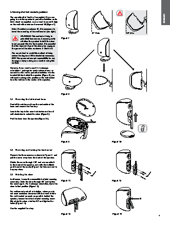
3 Moving the ball socket position
You can skip all of Section 3 completely if you are
going to use the speaker in portrait orientation on its                                                      ENGLISH
table stand as supplied, or you want to mount it high
on the wall with maximum downward tilt (Figure 7).
Note: To achieve maximum tilt, it is necessary to
invert the mounting of the wall bracket. (far right)
27° max                 40° max
WARNING! This method of fixing is
potentially less secure, because gravity   Figure 7
will allow the product to fall if the stem
is not properly fitted to the bracket. It is essential
that the tapered ridge of the clamp bar engages
the groove of the stem as shown in Section 5.
You are advised to avoid this method of fixing
unless the degree of tilt is absolutely necessary.
B&W Group cannot accept responsibility for any
damage or injury arising as a result of using this
method.
However, if you want to use it in landscape
orientation – perhaps for centre channel use – or
mount it on the wall in portrait orientation with the
bracket hidden behind the speaker (Figure 8), you
will need to change the position of the ball socket
from the bottom to the centre of the speaker.
Figure 8
3.1  Removing the table stand base
Peel off the rubber mat from the underside of the
base and remove the Torx key.
Locate the key in the cam-lock device and turn it
anti-clockwise to unlock the stem (Figure 9).
Part the base from the speaker (Figure 10).
Figure 9                            Figure 10
3.2  Removing and turning the back cover
Remove the three screws as shown in Figure 11 and
pull the cover away from the back of the speaker.
Rotate the cover through 180? and re-assemble it
to the back of the speaker, now with the ball joint
positioned at the centre (Figure 12). Take care not to
trap any wires.
3.3  Rotating the stem
In all cases, loosen the accessible ball joint securing
screw (A), rotate the stem through 90? and tighten   Figure 11          Figure 12
the screw again. For landscape orientation, leave the
stem in that position (Figure 13).
For wall-mount portrait  orientation, where you do
not need maximum downward tilt and want to hide
the wall bracket as much as possible behind the
speaker, loosen the other ball joint securing screw                                        B
(B), rotate the stem a further 90? and tighten the
screw (Figure 14).
Use the supplied Torx key.
A
Figure 13                           Figure 14
4