На сайте 123411 инструкций общим размером 499.36 Гб , которые состоят из 6235346 страниц
Фото
Руководство пользователя TRIPP LITE SU6000RT4UHVHW. Основные функции, характеристики и условия эксплуатации изложены на 116 страницах документа в pdf формате.
Доступно к просмотру 116 страниц. Рекомендуем вам скачать файл инструкции, поскольку онлайн просмотр документа может сильно отличаться от оригинала.
Warranty                      Owner’s Manual
chance to win a FREE Tripp Lite
Registration:
product—www.tripplite.com/warranty
register online today for a
SmartOnline™
Single-Phase 5kVA–6kVA
Intelligent True On-Line UPS Systems (Rackmount/Tower)
• Includes UPS system with internal battery system (5&6kVA), detachable PDU and detachable
parallel PDU modules (6kVA) • Rackmount and tower adaptable
Not suitable for mobile applications.
Important Safety Warnings                                                     2
Mounting                                                                      3
Features                                                                      4
Connection                                                                    9
Optional Connection                                                          12
Manual Bypass Operation                                                      14
Operation                                                                    15
Internal Battery Replacement                                                 28
Storage and Service                                                          29
Warranty and Warranty Registration                                           29
Espanol                                                                      30
Francais                                                                     59
?onneee                                                                      88
1111 W. 35th Street, Chicago, IL 60609 USA • www.tripplite.com/support
Copyright © 2012 Tripp Lite. All rights reserved. SmartOnline is a trademark of Tripp Lite.
1
201207113 933070.indb   1                                                                                  9/17/2012   1:19:41 PM
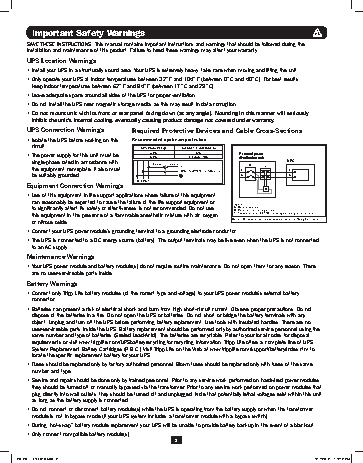
Important Safety Warnings
SAVE THESE INSTRUCTIONS. This manual contains important instructions and warnings that should be followed during the
installation and maintenance of this product. Failure to heed these warnings may affect your warranty.
UPS Location Warnings
•  Install your UPS in a structurally sound area. Your UPS is extremely heavy; take care when moving and lifting the unit.
•  Only operate your UPS at indoor temperatures between 32° F and 104° F (between 0° C and 40° C). For best results,
keep indoor temperatures between 62° F and 84° F (between 17° C and 29° C).
•  Leave adequate space around all sides of the UPS for proper ventilation.
•  Do not install the UPS near magnetic storage media, as this may result in data corruption.
•  Do not mount unit with its front or rear panel facing down (at any angle). Mounting in this manner will seriously
inhibit the unit’s internal cooling, eventually causing product damage not covered under warranty.
UPS Connection Warnings               Required Protective Devices and Cable Cross-Sections
•  Isolate the UPS before working on this    Recommended upstream protection
circuit.                               UPS Power Rating  Upstream Circuit Breaker
N/A
•  The power supply for this unit must be    5kVA         C curve - 40A     External power
6kVA
distribution unit
single-phase rated in accordance with      2 poles circuit breaker            Q            UPS
the equipment nameplate. It also must               L1  To UPS Normal AC source  L  T       L
L2(N)
be suitably grounded.                                                      N                N
G L2(N) L1
Equipment Connection Warnings
B
•  Use of this equipment in life support applications where failure of this equipment
can reasonably be expected to cause the failure of the life support equipment or    Legend
to significantly affect its safety or effectiveness is not recommended. Do not use    B—Contactor solenoid.
Q—Mains input thermal-magnetic switch.
this equipment in the presence of a flammable anesthetic mixture with air, oxygen    T—Two-pole contactor 100 A AC1; coil voltage: according to the mains input.
or nitrous oxide.                                                       Remark: Q needs to use the approved component of Safety Certification.
•  Connect your UPS power module’s grounding terminal to a grounding electrode conductor.
•  The UPS is connected to a DC energy source (battery). The output terminals may be live even when the UPS is not connected
to an AC supply.
Maintenance Warnings
•  Your UPS power module and battery module(s) do not require routine maintenance. Do not open them for any reason. There
are no user-serviceable parts inside.
Battery Warnings
•  Connect only Tripp Lite battery modules (of the correct type and voltage) to your UPS power module’s external battery
connector.
•  Batteries can present a risk of electrical shock and burn from high short-circuit current. Observe proper precautions. Do not
dispose of the batteries in a fire. Do not open the UPS or batteries. Do not short or bridge the battery terminals with any
object. Unplug and turn off the UPS before performing battery replacement. Use tools with insulated handles. There are no
user-serviceable parts inside the UPS. Battery replacement should be performed only by authorized service personnel using the
same number and type of batteries (Sealed Lead-Acid). The batteries are recyclable. Refer to your local codes for disposal
requirements or visit www.tripplite.com/UPSbatteryrecycling for recycling information. Tripp Lite offers a complete line of UPS
System Replacement Battery Cartridges (R.B.C.).Visit Tripp Lite on the Web at www.tripplite.com/support/battery/index.cfm to
locate the specific replacement battery for your UPS.
•  Fuses should be replaced only by factory authorized personnel. Blown fuses should be replaced only with fuses of the same
number and type.
•  Service and repair should be done only by trained personnel. Prior to any service work performed on hardwired power modules,
they should be turned off or manually bypassed via the transformer. Prior to any service work performed on power modules that
plug directly into wall outlets, they should be turned off and unplugged. Note that potentially lethal voltages exist within this unit
as long as the battery supply is connected.
•  Do not connect or disconnect battery module(s) while the UPS is operating from the battery supply or when the transformer
module is not in bypass mode (if your UPS system includes a transformer module with a bypass switch).
•  During “hot-swap” battery module replacement your UPS will be unable to provide battery backup in the event of a blackout.
•  Only connect compatible battery module(s).
2
201207113 933070.indb   2                                                                                  9/17/2012   1:19:42 PM
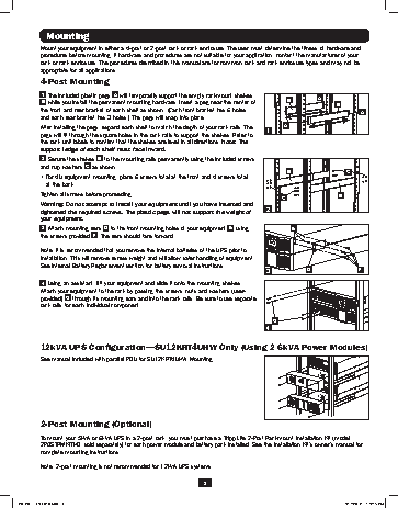
Mounting
Mount your equipment in either a 4-post or 2-post rack or rack enclosure. The user must determine the fitness of hardware and
procedures before mounting. If hardware and procedures are not suitable for your application, contact the manufacturer of your
rack or rack enclosure. The procedures described in this manual are for common rack and rack enclosure types and may not be
appropriate for all applications.
4-Post Mounting
1  The included plastic pegs  A  will temporarily support the empty rackmount shelves    A
B  while you install the permanent mounting hardware. Insert a peg near the center of   B       B
the front and rear bracket of each shelf as shown. (Each front bracket has 6 holes                       A
and each rear bracket has 3 holes.) The pegs will snap into place.
After installing the pegs, expand each shelf to match the depth of your rack rails. The   1  A
pegs will fit through the square holes in the rack rails to support the shelves. Refer to
the rack unit labels to confirm that the shelves are level in all directions. Note: The
support ledge of each shelf must face inward.
2  Secure the shelves  B  to the mounting rails permanently using the included screws
and cup washers  C  as shown.
B                   C
• For 4U equipment mounting, place 6 screws total at the front and 4 screws total
at the back.
Tighten all screws before proceeding.
C                 B
Warning: Do not attempt to install your equipment until you have inserted and
tightened the required screws. The plastic pegs will not support the weight of   2
your equipment.
3  Attach mounting ears  D  to the front mounting holes of your equipment  E  using   E
the screws provided  F . The ears should face forward.
Note: It is recommended that you remove the internal batteries of the UPS prior to
installation. This will remove excess weight and will allow safer handling of equipment.
See Internal Battery Replacement section for battery removal instructions.
3             D                F
4  Using an assistant, lift your equipment and slide it onto the mounting shelves.
Attach your equipment to the rack by passing the screws, nuts and washers (user-
provided)  G  through its mounting ears and into the rack rails. Be sure to use separate
rack rails for each individual component.
G
4
12kVA UPS Configuration—SU12KRT4UHW Only (Using 2 6kVA Power Modules)
See manual included with parallel PDU for SU12KRT4UHW Mounting.                          SW
SW
14
14
2-Post Mounting (Optional)
To mount your 5kVA or 6kVA UPS in a 2-post rack, you must purchase a Tripp Lite 2-Post Rackmount Installation Kit (model:
2POSTRMKITHD, sold separately) for each power module and battery pack installed. See the Installation Kit’s owner’s manual for
complete mounting instructions.
Note: 2-post mounting is not recommended for 12kVA UPS systems.
3
201207113 933070.indb   3                                                                                  9/17/2012   1:19:45 PM