На сайте 123431 инструкция общим размером 499.45 Гб , которые состоят из 6236163 страниц
Фото
Руководство пользователя TRIPP LITE PDUBHV20. Основные функции, характеристики и условия эксплуатации изложены на 28 страницах документа в pdf формате.
Доступно к просмотру 28 страниц. Рекомендуем вам скачать файл инструкции, поскольку онлайн просмотр документа может сильно отличаться от оригинала.
chance to win a FREE Tripp Lite   Owner’s Manual
register online today for a
Warranty
Registration:
product—www.tripplite.com/warranty
Hot-Swap PDU
with Maintenance Bypass Switch
Models: PDUB15, PDUB20, PDUB30, PDUBHV10, PDUBHV20
Important Safety Warnings                                                                          2
Mounting                                                                                           2
Features                                                                                           4
Connection & Operation                                                                             6
Troubleshooting                                                                                    7
Service, Warranty & Warranty Registration                                                          7
Espanol                                                                                            8
Francais                                                                                          15
???????                                                                                           22
1111 W. 35th Street, Chicago, IL 60609 USA
www.tripplite.com/support
Copyright © 2009 Tripp Lite. All trademarks are the sole property of their respective owners.
1
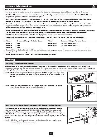
Important Safety Warnings
SAVE THESE INSTRUCTIONS
This manual contains important instructions and warnings that should be followed during the installation and operation of this product.
•   Install the PDU indoors, away from excess moisture or heat, direct sunlight, dust or conductive contaminants. Do not install the PDU near
magnetic storage media, as this may cause data corruption.
•   Only operate the PDU at indoor temperatures between 32° F and 104° F (0 °C and 40° C). For best results, maintain indoor temperatures
between 62° F and 84° F (17° C and 29° C). For proper ventilation, leave adequate space around all sides of the PDU.
•   Use of this equipment in life support applications where failure of this equipment can reasonably be expected to cause the failure of the life
support equipment or to significantly affect its safety or effectiveness is not recommended. Do not use this equipment in the presence of a
flammable anesthetic mixture with air, oxygen or nitrous oxide.
•   Do not connect the PDU to an ungrounded outlet or to adapters that eliminate the connection to ground. The ground connections are provided
for your safety. If the provided plug does not fit your outlet, have a compatible grounded outlet installed by a qualified electrician.
•   The PDU must be installed near the wall outlet and all plugs must be readily accessible for disconnection.
•   The PDU must be connected to a wall outlet that is protected by an overcurrent device with the rating shown in the table below:
Model        Overcurrent Rating of Protection Device   Model      Overcurrent Rating of Protection Device
PDUB15       20A                                 PDUBHV10      20A (cTUVus) or 16A (CE)
PDUB20       20A                                 PDUBHV20      20A (cTUVus) or 16A (CE)
PDUB30       30A
•   Caution! Risk of electrical shock! The PDU is supplied by more than one power source. All power sources must be disconnected to de-
energize the unit before servicing.
•   Do not open the PDU for any reason. There are no user-serviceable parts inside.
Mounting
Mounting (2-Post or 4-Post Racks)
Mount the equipment in either a 2-post or 4-post open frame rack or rack enclosure. The user must determine the fitness of hardware and
procedures before mounting. The procedures described in this manual are for common rack and rack enclosure types and may not be appropriate
for all applications. Note: Mounting procedures are the same for both 2-post and 4-post rack installation.
Step 1.  Attach the mounting ears to the mounting holes of the PDU using the screws provided.
The ears should face forward. Note: The top or bottom mounting holes of the PDU can
be used.
Mount in top or
Step 1               bottom holes.
Step 2.  Attach the PDU to the rack with user-provided screws, nuts and washers. Insert the
screws through the mounting ears and into the rack rails.
Step 2
Mounting in the Same Rack Space as a UPS System (4-Post Racks)
The Hot-Swap PDU can be mounted in the same rack space as a UPS system when the UPS
system is mounted using Tripp Lite’s 4POSTRAILKIT. (4POSTRAILKIT is included with
most Tripp Lite UPS systems and is also sold separately. Refer to the UPS system manual or
4POSTRAILKIT manual for UPS system mounting instructions. The procedure for mounting
the rear of the 4POSTRAILKIT mounting shelves to the rack will differ slightly, as shown in this
section.)
Step 1.  Attach the mounting ears to the lower mounting holes of the unit using the screws
provided. The ears should face forward.                          Step 1
2
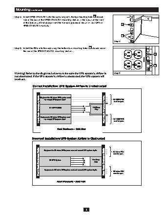
Mounting (continued)
Step 2.  Install 4POSTRAILKIT into the rack using only the top mounting hole  A  at each
side of the rear of the 4POSTRAILKIT mounting shelves. (The screws at the front
of the shelves will not change from the standard procedure shown in your UPS or
4POSTRAILKIT manual.)                                                    A
B
Step 2
Step 3.  Install the PDU into the rack using the bottom two mounting holes  B  at each side of
UPS
the rear of the 4POSTRAILKIT mounting shelves.  AVAILABLE  MAINTENANCE BYPASS  LINE CORD HERE  12A MAX.
CONNECT UPS
AVAILABLE
UPS         UTILITY                                          A
26
OUTPUT
25  B
UTILITY
TO UPS OUTPUT
12A MAX.
Warning! Refer to the diagrams below to make sure the UPS system’s airflow is   Step 3
not obstructed. If the UPS system’s airflow is obstructed, the UPS system will                      24
overheat.
3