На сайте 123431 инструкция общим размером 499.45 Гб , которые состоят из 6236163 страниц
Фото
Руководство пользователя TRIPP LITE APSX4048SW. Основные функции, характеристики и условия эксплуатации изложены на 48 страницах документа в pdf формате.
Доступно к просмотру 47 страниц. Рекомендуем вам скачать файл инструкции, поскольку онлайн просмотр документа может сильно отличаться от оригинала.
Owner’s Manual
Sine Wave DC-to-AC Inverter/Charger
Model: APSX4048SW
48 VDC to 230 VAC
Table of Contents
Important Safety Instructions       2             5.   Inverter/Charger 3-Phase      13
1.   Overview & Features            3                 Parallel Installation
1.1  Overview                       3             5.1   Installation                 13
1.2   Front Panel Controls, LCD Screen    3       5.2   Installation Diagrams and Charts   13
and LED Indicators                            5.3  Installation and Start-Up     14
1.3   Optional Features             4             6.   Operation                     16
2.   Battery Charger                4             6.1   Modes of Operation           16
2.1   Mode of Operation             4                 (Single and 3-Phase)
2.2   Transfer Switching Speed      4             6.2   Settings and Parameters      18
3.   Battery Installation           4             6.3  Single-Phase Parallel Operation   20
and Maintenance                               6.4  3-Phase Parallel Operation    21
3.1   Select Battery Type           4             7.   Technical Specifications      22
3.2   Monthly Maintenance           6             8.   Troubleshooting               22
3.3   Battery Installation          6             9.   Service                       23
3.4   Battery Connection            6             Русский                            24
4.   Inverter/Charger Single-Phase   9
Installation
4.1   Installation                  9
4.2   Installation Diagrams and Charts   9
4.3  Installation and Start-Up     10
4.4   Single-Phase Parallel Stacking    11
Installation and Start-Up
PROTECT YOUR INVESTMENT!
Register your product for quicker service and ultimate peace of mind.
You could also win an ISOBAR6ULTRA surge protector—a $50 value!
www.tripplite.com/warranty
1111 W. 35th Street, Chicago, IL 60609 USA • www.tripplite.com/support
Copyright © 2014 Tripp Lite.
1
Important Safety Instructions
SAVE THESE INSTRUCTIONS!
This manual contains important instructions and warnings that should be followed during the installation,
operation and storage of all Tripp Lite Inverter/Chargers.
Location Warnings
• Do not mount unit with its front or rear panel facing down (at any angle). Mounting in this manner will seriously
inhibit the unit’s internal cooling, eventually causing product damage not covered under warranty.
• Install your Inverter/Charger in a location or compartment that minimizes exposure to heat, dust, direct sunlight and
moisture. Flooding the unit with water will cause it to short-circuit and could cause personal injury due to electric shock.
• For proper ventilation, allow a minimum 2 inches of clearance at front and back of the Inverter/Charger. To avoid overheating
the Inverter, the compartment that houses the Inverter/Charger must be properly ventilated with adequate outside air flow.
The heavier the load of connected equipment, the more heat will be generated by the unit.
• Do not install the Inverter/Charger near magnetic storage media, as this may result in data corruption.
• Do not install the Inverter/Charger near flammable materials, fuel or chemicals.
Battery Connection Warnings
• Multiple battery systems must be comprised of batteries of identical voltage, age, amp-hour capacity and type.
• Because explosive hydrogen gas can accumulate near batteries if they are not well ventilated, do not install batteries in a
“dead air” compartment. The battery compartment should have some ventilation to outside air.
• Sparks may result during final battery connection. Always observe proper polarity as batteries are connected.
• Do not allow objects to contact the DC input terminals. Do not short or bridge these terminals together. Serious personal
injury or property damage could result.
Ground Connection Warnings
•  Safe operation requires connecting the Inverter/Charger’s Main Ground Terminal directly to the frame of the vehicle or
earth ground.
Equipment Connection Warnings
• Use of this equipment in life support applications where failure of this equipment can reasonably be expected to cause
the failure of the life support equipment or to significantly affect its safety or effectiveness is not recommended. Do not
use this equipment in the presence of a flammable anesthetic mixture with air, oxygen or nitrous oxide.
• You may experience uneven performance results if you connect a surge suppressor, line conditioner or UPS system to the
output of the Inverter/Charger.
• User must supply proper protection for wire openings in unit panels.
Operation Warnings
• Your Inverter/Charger does not require routine maintenance.
• Potentially lethal voltages exist within the Inverter/Charger as long as the battery supply is connected. During any service
work, the battery supply should therefore be disconnected.
• Do not connect or disconnect batteries while the Inverter/Charger is operating from the battery supply. Dangerous arcing may
result.
2
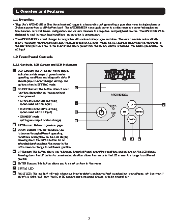
1. Overview and Features
1.1 Overview
•  Tripp Lite’s APSX4048SW Sine Wave Inverter/Charger is a heavy-duty unit generating a pure sine wave in single-phase or
3-phase power from a 48V battery bank. The APSX4048SW can supply power to a wide range of connected equipment,
from heaters, air conditioners, refrigerators and vacuum cleaners to computers and peripheral devices. The APSX4048SW is
designed to work in heavy load conditions, so de-rating is unnecessary.
•  The APSX4048SW’s smart charger is compatible with various battery types and sizes. The switch module automatically
diverts the energy transfer path between the Inverter and an AC input. When the AC source is lower than the transfer level,
the electrical path switches to the Inverter and draws power from the battery source. Otherwise, the load is powered by the
AC input.
1.2 Front Panel Controls
1.2.1 Controls, LCD Screen and LED Indicators
1   LCD Screen: This 2-line dot matrix display
indicates a wide range of power inverter
operating conditions and diagnostic data. It
also displays Inverter/Charger settings and
options when in SETTING mode.
2   ON/OFF Button: This button offers 3 main   1
functions depending on the power input
when pressed:                                                     APSX4048SW
• CHARGING/STANDBY switching
(when used with AC input).             7                                      UP                     6
Status
• INVERTING/STANDBY switching
(when used with DC input).             2                         Fault   SET      ENTER
• STANDBY mode
(AC bypass output and no charge).      8                                     DOWN
3   SET Button: Return to previous page.
4   DOWN Button: This button allows you
to browse through different operating
conditions and options on the LCD display.
Pressing down the DOWN button for an                                      3     4    5
extended duration allows the cursor in the
LCD screen to change to a different position.
5   UP Button: This button allows you to browse through different operating conditions and options on the LCD display.
Pressing down the UP button for an extended duration allows the cursor in the LCD screen to change to a different
position.
6   ENTER Button: This button allows you to select an item in the menu.
7   STATUS LED
8   FAULT LED: This red light will flash when your inverter detects an internal fault (overheating, overvoltages, etc.) or when it
detects a wiring fault from the AC or DC power source (reversed phases, missing ground, etc.).
3