На сайте 123431 инструкция общим размером 499.45 Гб , которые состоят из 6236163 страниц
Фото
Руководство пользователя TRIPP LITE APSINT2012. Основные функции, характеристики и условия эксплуатации изложены на 48 страницах документа в pdf формате.
Доступно к просмотру 48 страниц. Рекомендуем вам скачать файл инструкции, поскольку онлайн просмотр документа может сильно отличаться от оригинала.
WARRANTY
a chance to win a FREE Tripp Lite
Register online today for
REgISTRATION                                 Owner’s Manual
product! www.tripplite.com/warranty
PowerVerter
®
APS Series DC-to-AC
Inverter/Charger
APS Models - - 12, - - 24 and - - 36VR    APSINT Models - - 12, - - 24 and - - 36VR
Input          Output                     Input           Output          1111 W. 35th Street, Chicago, IL 60609 USA
Customer Support: 773.869.1234
Invert:    12/24/36 VDC*    120V, 60 Hz. AC  Invert:   12/24/36 VDC*   230V, 50 Hz. AC      www.tripplite.com
Charge:   120V, 60 Hz. AC   12/24/36 VDC*  Charge:  230V, 50 Hz. AC   12/24/36 VDC*
*Voltage determined by respective model number.
Reliable Emergency Backup Power
Congratulations! You've purchased the most advanced, feature-rich Inverter/Charger designed as an alternative energy source during utility
power  failures.  Tripp  Lite APS  Inverter/Chargers  keep  your  equipment  up  and  productive  through  all  utility  power  problems  (blackouts,
brownouts and overvoltages) by inverting DC power from user-supplied batteries into AC power. When utility power is present, APS Inverter/
Chargers automatically pass through power to your equipment while simultaneously recharging your connected battery bank. Built-in surge
suppression provides an additional level of equipment protection. APS Inverter/Chargers are the quiet alternative to gas generators for emergency
backup applications. You get AC electricity anywhere and anytime you need it—with no fumes, fuel or noise!
Better for Your Equipment                                Premium Protection Levels
•  Built-In ISOBAR  Surge Protection
®
•  Automatic Overload Protection
Ideal Output for All Loads
•  Frequency-Controlled Output
•  Automatic Load Switching
•  Balanced Load Sharing
Better for Your Batteries                                Faster Battery Recharge
•  High-Amp, 3-Stage Battery Charger (adjustable)
Critical Battery Protection
•  Battery Charge Conserver (Load Sense)
•  Battery Temperature Sensing
•  High-Efficiency DC-to-AC Inversion
Better for You                                           Quiet, Simple, Maintenance-Free Operation
•  Multi-Function Lights & Switches
•  Moisture-Resistant Construction*
Contents
Safety                                          2          AC Input/Output Connection                       11
Feature Identification                          3          Service/Maintenance                              11
Operation                                       4-5        Troubleshooting                                  12
Configuration                                   5-7        Warranty/Warranty Registration                   12
Battery Selection                               8          Espanol                                          13
Mounting                                        9          Francais                                         25
Battery Connection                              10         ???????                                          37
* Inverter/Chargers are moisture-resistant, not waterproof.
Copyright © 2009. All rights reserved. PowerVerter  and Isobar  are registered trademarks of Tripp Lite.
®
®
Important Safety Instructions
SAVE THESE INSTRUCTIONS!
This manual contains important instructions and warnings that should be followed during the installation, operation and storage of this
product.
Location Warnings
•  Install your Inverter/Charger in a location or compartment that minimizes exposure to heat, dust, direct sunlight and moisture.
•  Although your Inverter/Charger is moisture resistant, it is NOT waterproof. Flooding the unit with water will cause it to short circuit
and could cause personal injury due to electric shock. Never immerse the unit, and avoid any area where standing water might
accumulate. Mounting should be in the driest location available.
•  Leave a minimum of 50 mm clearance at front and back of the Inverter/Charger for proper ventilation. To avoid automatic Inverter/Charger
shutdown due to overtemperature, any compartment that contains the Inverter/Charger must be properly ventilated with adequate outside air
flow. The heavier the load of connected equipment, the more heat will be generated by the unit.
•  Do not install the Inverter/Charger directly near magnetic storage media, as this may result in data corruption.
•  Do not install near flammable materials, fuel or chemicals.
•  Do not mount unit with its front or rear panel facing down (at any angle). Mounting in this manner will seriously
inhibit the unit's internal cooling, eventually causing product damage not covered under warranty.
Battery Connection Warnings
•  The battery should be connected before operating the Inverter/Charger.
•  Multiple battery systems must be comprised of batteries of identical voltage, age, amp-hour capacity and type.
•  Because explosive hydrogen gas can accumulate near batteries if they are not kept well ventilated, your batteries should not be
installed (whether for a mobile or stationary application) in a “dead air” compartment. Ideally, any compartment would have some
ventilation to outside air.
•  Sparks may result during final battery connection. Always observe proper polarity as batteries are connected.
•  Do not allow objects to contact the two DC input terminals. Do not short or bridge these terminals together. Serious personal injury
or property damage could result.
Equipment Connection Warnings
•  Use of this equipment in life support applications where failure of this equipment can reasonably be expected to cause the
failure of the life support equipment or to significantly affect its safety or effectiveness is not recommended. Do not use this
equipment in the presence of a flammable anesthetic mixture with air, oxygen or nitrous oxide.
•  Only connect your Inverter/Charger to a properly grounded hardwired AC power source. Do not plug the unit into itself; this will
damage the device and void your warranty.
•  You may experience uneven performance if you connect a surge suppressor, line conditioner or UPS system to the output of your
Inverter/Charger.
Operation Warnings
•  Your Inverter/Charger does not require routine maintenance. Do not open the device for any reason. There are no user serviceable parts inside.
•  Potentially lethal voltages exist within the Inverter/Charger as long as the battery supply and/or AC input are connected. During any
service work, the battery supply and AC input connection (if any) should therefore be disconnected.
•  Do not connect or disconnect batteries while the Inverter/Charger is operating in either inverting or charging mode. Operating Mode
Switch should be in the DC OFF position. Dangerous arcing may result.
Caution: Your Inverter/Charger has a failsafe AC pass-through feature. The AC output will be live (if AC input is
available) even though the operating mode switch is set to DC OFF.
2
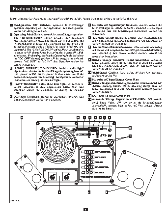
Feature Identification
Identify the premium features on your specific model and quickly locate instructions on how to maximize their use.
1  Configuration  DIP  Switches:  optimize  Inverter/Charger   6  Hardwire AC Input/Output Terminals: securely connect the
operation  depending  on  your  application.  See  Configuration    Inverter/Charger  to  vehicle  or  facility  electrical  system  input
section for setting instructions.                         and  output.  See  AC  Input/Output  Connection  section  for
2  Operating Mode Switch: controls Inverter/Charger operation.    instructions.
The  “AUTO/REMOTE”  setting  ensures  your  equipment    7  Resettable  Circuit  Breakers:  protect  your  Inverter/Charger
receives constant, uninterrupted AC power. It also enables the    against damage due to overload or charger failure. See Operation
Inverter/Charger to be remotely monitored and controlled with    section for resetting instructions.
an optional remote module (Tripp Lite model APSRM4, sold   8  Remote Control Module Connector: allows remote monitoring
separately). The “CHARGE ONLY” setting allows your batteries   and control with an optional module (Tripp Lite model APSRM4,
to return to full charge faster by turning the inverter off which   sold  separately).  See  remote  module  owner’s  manual  for
halts battery discharging. Setting the Operating Mode Switch to   connection instructions.
the "DC OFF" (center) position will de-energize the unit and   Battery  Charge  Conserver  (Load  Sense) Dial:  conserves
connect  "AC  OUT"  to  "AC  IN."  See  Operation  section  for   9  battery power by setting the low-load level at which the Inverter/
setting instructions.                                     Charger’s  inverter  automatically  shuts  off.  See  Configuration
3  “LINE”, “INVERT”, “LOAD” LEDs: intuitive “traffic light”    section for setting instructions.
signals show whether the Inverter/Charger is operating from AC   Multi-Speed  Cooling  Fan:  quiet,  efficient  fan  prolongs
line    power  or  DC  battery  power.  It  also  warns  you  if  the    10  equipment service life.
connected equipment load is too high. See Operation section for
instructions on reading the indicator lights.          11  Hardwire AC Input/Output Cover Plate
4  "BATT VOLTAGE" LEDs: these three lights will turn on in   12  Battery Temperature Sensing Connector (side mounted, not
several  sequences  to  show  approximate  battery  level.  See   shown):  prolongs  battery  life  by  adjusting  charge  based  on
Operation  section  for  instructions  on  reading  the  indicator   battery temperature. Use with included cable. See Configuration
lights.                                                   section for details.
5  DC Power Terminals: connect to your battery terminals. See    13  DC Power Terminal Cover Plate
Battery Connection section for instructions.           14  Automatic  Voltage  Regulation  (AVR)  LEDs:  (VR  models
only)  These  lights  will  turn  on  as  the  Inverter/Charger
automatically  corrects  high  or  low  AC  line  voltage  without
draining the battery.
13                    10                 14   1   4   8   3  2   9
12
7
5                     6            11
Front View
3